HYBRID/TROUBLE SHOOTING
3–464
4
Inspecting the
PCU wire har-
ness (upper
side) for conti-
nuity
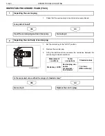
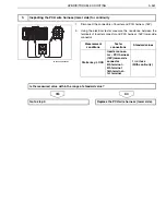
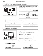
1. Using the electrical tester, mea-
sure the resistance between
the terminals of service plug
connector and PCU harness
(16P) upper-side connector.
<Measurement conditions>
Starter key: LOCK
<Tester connections>
Service plug connector – PCU
harness (16P) connector
1st terminal – 1st terminal
2nd terminal – 5th terminal
<Standard values>
1
or less (With continuity)
The mea-
sured value is
within the
range of stan-
dard value: Go
to YES.
The mea-
sured value is
not within the
range of stan-
dard value: Go
to NO.
Go to step 5.
Replace the
main wire har-
ness in the HV
battery.
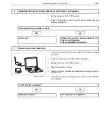
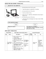
5
Reproduction
check [HINO-
DX]
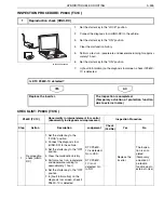
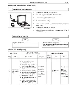
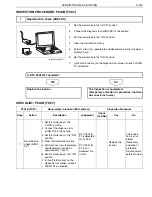
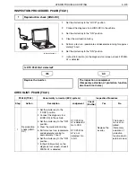
1. Connect all the connectors that
have been disconnected to
restore the system.
2. Connect the diagnosis tool
(HINO-DX) to the vehicle.
3. Set the starter key to the "ON"
position.
4. Clear the malfunction history
and set the starter key to the
"LOCK" position.
5. Set the starter key to the "ON"
position again.
6. In [Fault Information] on the
diagnosis tool screen, check if
P0A0D-20 is detected.
DTC P0A0D-
20 is detected:
Go to YES.
DTC P0A0D-
20 is not
detected: Go
to NO.
Replace the
inverter.
The inspec-
tion is com-
pleted.
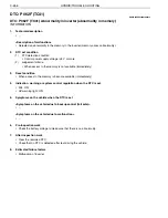
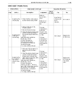
P0A0D (TC20)
Abnormality in ILK input
Inspection Procedure
Step
Action
Description
Judgement
Check
(Yes/No)
Yes
No


