HYBRID/TROUBLE SHOOTING
3–11
5.
TROUBLE SHOOTING PROCEDURE
(1)
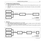
Trouble shooting procedure (when using genuine Hino service tool)
a.
Check the DTC of the HV ECU using the service tool (trouble shooting tool).
b.
Record the DTC and TC No. (detailed DTC) of freeze frame data.
c.
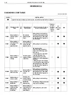
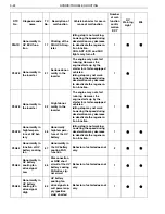
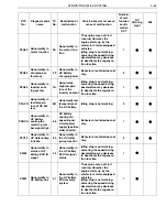
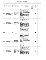
Perform trouble shooting for the relevant DTC. For an inverter/HV battery line malfunction, read the DTC of
each ECU for trouble shooting according to the HV ECU diagnostic chart.
d.
After trouble shooting, delete the DTC of each ECU using the service tool and conduct a trial running to check
that the malfunction does not recur.
! CAUTION
• When inspecting the high voltage line, wear insulating gloves because of a risk of electrical shock. Before per-
forming inspection, be sure to remove the service plug after the starter key is turned to the "LOCK" position.
When inspecting the HV battery, wear safety glasses.
Do not touch the terminals of the high voltage line for 7 minutes after removing the service plug.
• One diagnosis code (DTC) may contain more than 1 malfunction. Read TC No. (detailed DTC) of freeze frame
data with the trouble shooting tool and perform trouble shooting according to the relevant trouble shooting
chart.
• When inspecting the harness, first check the connector for fitting looseness, and the fitting surface for entry of
foreign matters.
• There may be irregular contact or temporary noise due to partial fitting of the connector if parts are returned to
normal without repairing or replacing parts using the diagnostic chart.
• The service tool or trouble shooting tool described in the trouble shooting chart indicates the genuine Hino ser-
vice tool.
• If the starter key is turned "ON" in the state that connectors, etc. are disconnected while performing the trouble
shooting chart, the malfunction may be recorded due to disconnection of a connector. In such case, be sure to
delete the diagnosis code using the trouble shooting tool.
HINT
If there is no malfunction and the engine does not stop with the idling stop function, the following cases are con-
ceivable.
• A vehicle is not running at vehicle speed of 5 km/h or more from the last idling stop.
• The change lever is located at a position other than "D" and "4".
• When the turn signal light and the hazard light are ON. (Even if the turn signal light switch signal and the hazard
light switch signal transmitted to the HV ECU are Low, the engine does not stop automatically by use of the
idling stop function.)
• When a vehicle stopped on a sloped road.
• While PTO is operating.
• While DPR is operating.
• Capacity of the HV battery is low.
• Engine coolant temperature is low.
• The engine is still running. (The engine is running at approximately 1 km/h or more.)
• When the status of the idling stop cancel switch is "ON".
• Brake vacuum pressure is low. (Even if the low brake vacuum pressure switch signal transmitted to the HV ECU
becomes Low, the engine does not stop automatically by use of the idling stop function.)


