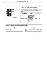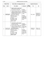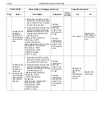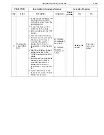
HYBRID/TROUBLE SHOOTING
3–207
7
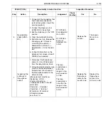
Inspecting the
insulation
resistance of
high-voltage J/
B (in the bat-
tery pack)
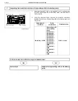
1. Disconnect the BATT OUT (+)
[5] and BATT OUT (-) [6] termi-
nals from the high-voltage J/B
(in the battery pack), and then
remove the frame wire.
2. Using the electrical tester, mea-
sure the insulation resistance
between the terminals of high-
voltage J/B (in the battery pack)
and the ground.
<Measurement conditions>
Starter key: LOCK
<Tester connections>
High-voltage J/B (in the battery
pack)
3rd terminal
–
4th terminal
5th terminal
–
6th terminal
3rd terminal
–
6th terminal
4th terminal
–
5th terminal
3rd terminal
–
GND
4th terminal
–
GND
5th terminal
–
GND
6th terminal
–
GND
<Standard values>
10 M
or more
The mea-
sured value is
within the
range of stan-
dard value: Go
to YES.
The mea-
sured value is
not within the
range of stan-
dard value: Go
to NO.
Go to step 8.
Replace the
high-voltage J/
B (in the bat-
tery pack).
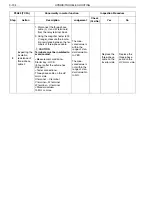
8
Inspecting the
insulation
resistance of
frame wire (to
the high-volt-
age J/B)
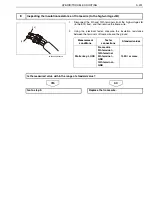
1. Disconnect the 9th and 10th
terminals from the high-voltage
J/B (in the ECU box), and then
remove the frame wire.
2. Using the electrical tester, mea-
sure the insulation resistance
between the terminals of frame
wire and the ground.
<Measurement conditions>
Starter key: LOCK
<Tester connections>
Frame wire
9th terminal
–
10th terminal
9th terminal
–
GND
10th terminal
–
GND
<Standard values>
10 M
or more
The mea-
sured value is
within the
range of stan-
dard value: Go
to YES.
The mea-
sured value is
not within the
range of stan-
dard value: Go
to NO.
Go to step 9.
Replace the
frame wire.
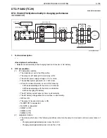
P0A92 (TC29)
Abnormality in charging performance
Inspection Procedure
Step
Action
Description
Judgement
Check
(Yes/No)
Yes
No

