NetWave DirectView Broadcast Console Operations & Technical Manual
Revision A
2 - Installation
Harris Broadcast
2-21
PR&E
●
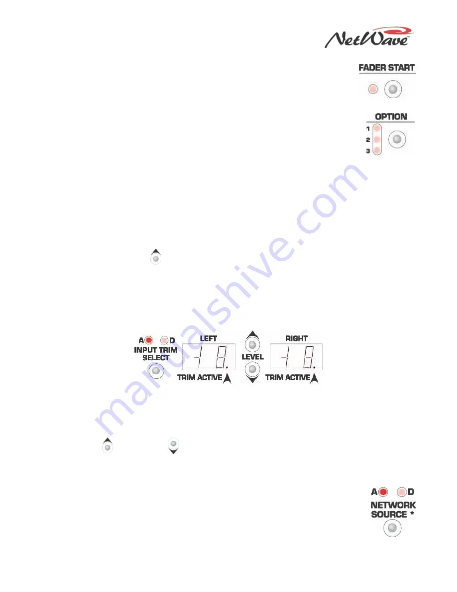
Fader Start — When the LED is unlit (the standard setting), the channel fader
position has no effect on the channel On/Off status. When the LED is lit, move the
fader to turn the channel on, moving the fader up from full Off. Return the fader to full
Off to turn the channel off. The channel On and Off buttons and the remote channel on
and off commands are not affected by the fader start setting.
●
Option — Use this button in combination with other setup buttons to place the DSP card
into a special operation mode, a test mode, or an alternate setup mode. The three
Option LEDs indicate that a special operating mode is active on that DSP card. All DSP
cards should typically have the same Option settings.
•
Option + Off LED Ctrl – Press this button combination to activate or turn off the
Program Button Protect Mode. When this setting is active (the Option 1 LED is lit), you must press a
Program assignment button twice quickly to change that button status on the eight faders on the
DSP card.
•
Option + Logic Active – Press this button combination to activate or turn off the Tally Output
Mode. When this setting is active (the Option 2 LED is lit), all eight Logic I/O connectors on that
DSP card use tally logic (sustained on and off tallies), regardless of device type, and the Pulse
Select button is disabled. When this setting is inactive (the Option 2 LED is unlit), the output logic
for Line and Telco devices are start and stop pulses and the Pulse Select button works normally.
•
Option + Store – Press this button combination to reset all eight channels and their A and B
Source parameters back to the factory default settings.
•
Option + Channel Up
– Press this button combination to change the DSP card controls to
Parameter Copy Mode so that one set of parameters can be quickly assigned to multiple channels.
•
Option + Input Trim Select – Press and hold this button combination to display the PROM revision
for that DSP card in the two trim displays. The left display shows “r” and the right display shows the
number of the PROM revision (for example, 9=rev I, 10=rev J, or 11=rev K).
●
Input Trim Select & Level Controls — Use these three buttons to independently trim or boost the left
or right inputs on the local analog and digital input, in steps of 1 dB, up to +/-15 dB.
•
Left and Right – These displays show the current gain or trim setting for the input source indicated
above the Input Trim Select button. When A is lit, the Analog input channels appear in the Left
and Right displays. When D is lit, the Digital input channels appear. A lit Trim Active decimal point
indicates which channel (Left or Right) can be adjusted. The Input Trim Select button steps
through the four input channels (analog left, analog right, digital left, digital right) changing the
Trim Active decimal point and the A and D LEDs.
•
Level Up
or Level Down
- Press these buttons to raise or lower the active channel (the Trim
Active decimal point is lit on that channel) in 1 dB steps. When the active source is assigned on the
channel and assigned to cue, if the console Aux meter shows the cue bus levels, you can use the
meter to adjust the incoming level. The level adjustments take place immediately.
●
Network Source — Only use this function when the console’s VistaMax Link is active.
One audio input from each channel — A (analog) or D (digital) — is set as a VistaMax
source. The selected input signal is sent to the VistaMax system over the Link cable.
These signals are available to be selected like any other VistaMax source signal. This
setting does not affect your use of the same source locally within the console.


