NetWave DirectView Broadcast Console Operations & Technical Manual
Revision A
1 - Introduction
Harris Broadcast
1-6
PR&E
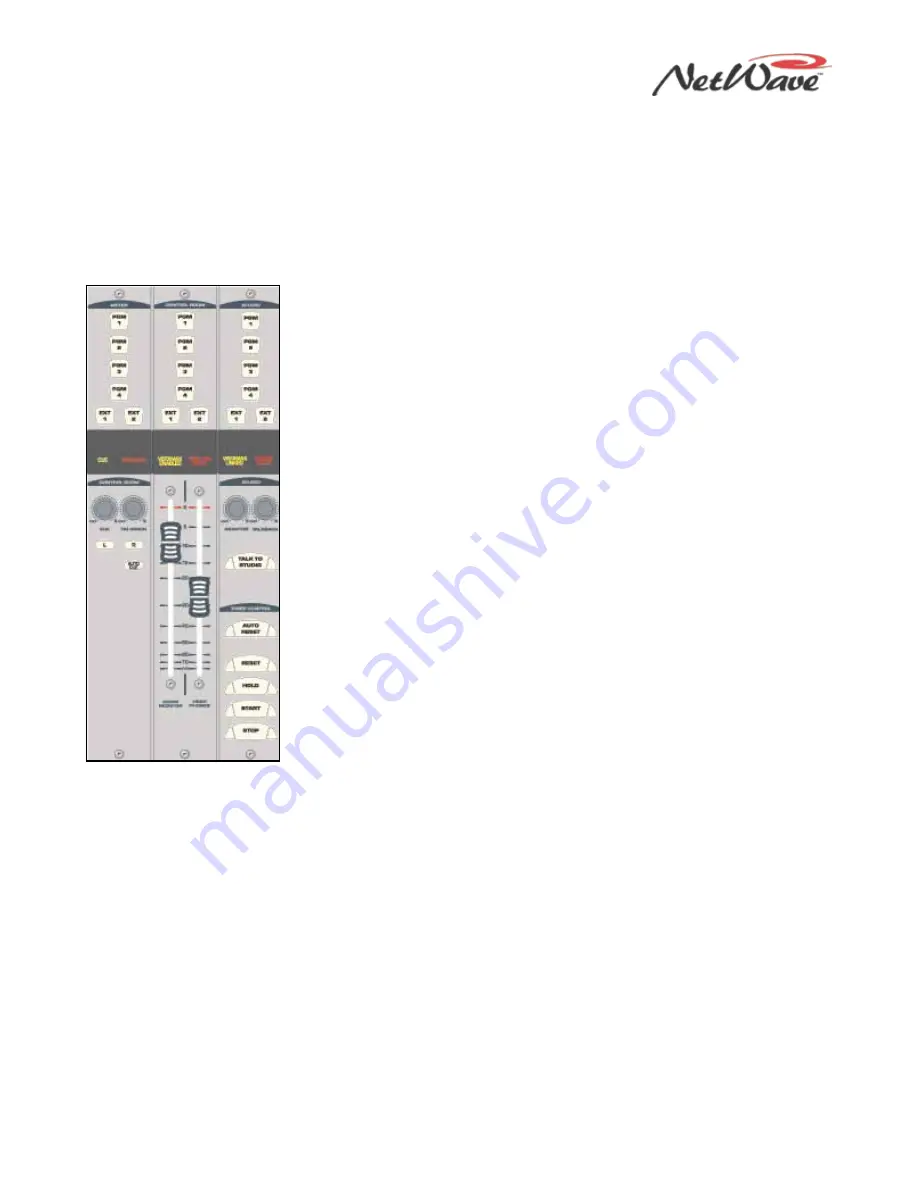
Figure 1-7. Monitor
Control Panel
Monitor Control Panel
This standard panel (Figure 1-7) is divided into three sections separated by double graphic lines. These
sections, listed from left to right and divided by main function, are
●
Auxiliary Meter section
●
Control Room (CR) section
●
Studio section
Auxiliary Meter Section
The top portion of all three sections has exclusive action source selector
buttons to select one monitor signal from between the PGM 1 thru 4 buses
and the two External Monitor inputs. In the Meter section, the buttons select
which signal feeds the right-most meter in the Console Display, with the
selected source name shown below the Auxiliary Meter. The Auxiliary Meter
is typically set to alternately show the cue levels while cue is active; the
Cue label lights, and the cue level is shown in the Auxiliary Meter section
with the name Cue below the meter.
Several CR controls are located below the meter selector buttons in this
section of the panel. The Control Room Section covers these controls.
Control Room Section
The middle of the panel has the Control Room (CR) monitor source selector
buttons and the two faders to adjust the level of the room monitor speakers
(left fader) and the operator headphone outputs (right fader). Any one
source can be selected, which feeds all control room monitor outputs. The
active source selection button lights to indicate it is active.
A cue speaker, mounted within the console display, is level controlled by the
Cue pot in the middle of the left-hand Auxiliary section of the panel. A
yellow Cue label, just above the pot, lights while cue is active on any
channel.
A Talkback pot controls the level of incoming talkback that feeds the cue
speaker, independently of the Cue volume pot. A red Talkback label, just
above the Talkback pot, lights when the control room is receiving talkback.
The Monitor Mode buttons, also in the left-hand section, below the cue and
talkback pots, set the signal mode for all CR and studio outputs. The L and
R buttons control whether the monitor outputs are stereo (neither button is
lit), left only (L is lit), right only (R is lit), or a mono sum signal (both are
lit).
Just below the R mode button is the AutoCue button. When this button is lit, the operator’s headphone
output automatically switches to feed the cue bus into the operator’s headphones when cue is active. When
unlit, cue activity does not affect the board operator’s headphone audio.
AutoCue has two operating modes (set by multi-switch DS1, switch 3 on the Monitor & Output card). The
default setting is Split Cue, where the cue audio goes to one ear and monitor audio is summed to the other
ear. This is typically used when the console is in an on-air studio. The alternate mode is Stereo Cue, where
stereo cue audio replaces the monitor audio source in the headphones. This setting is typically used in
production rooms and other off-air applications.
Studio Section
The right-hand section of the Monitor Control panel has the monitor source selection buttons and level
controls for a separate talk or voice studio. You can select a source from among the six buttons at the top of
this section. The active source button lights when selected.
The two pots in this section control the output level of a dedicated studio monitor output (Monitor) and the
amount of talk to studio audio (Talkback) that is fed to this monitor output.


