NetWave DirectView Broadcast Console Operations & Technical Manual
Revision A
1 - Introduction
Harris Broadcast
1-4
PR&E
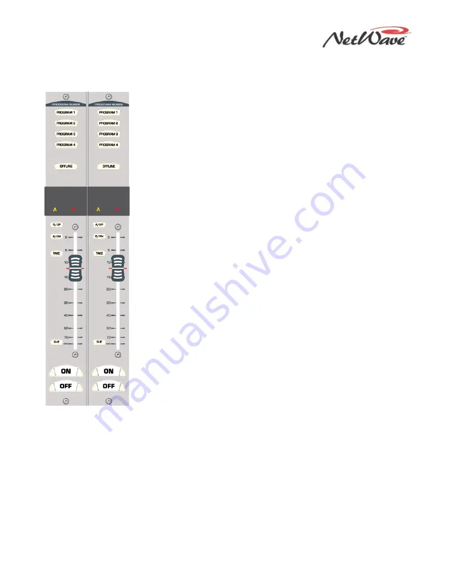
Figure 1-4. Dual Fader Panel
NetWave Dual Fader Panels
Each Dual Fader panel (Figure 1-4) has two fader channel control strips, each
with these features:
●
Separate Channel On and Channel Off illuminated buttons
●
A 100 mm fader for channel level control
●
Cue On/Off illuminated button
●
A/Up and B/Down source selection buttons with Take button
●
Active source illuminated label
●
Five bus assignment buttons (four Program and one Offline)
All channel control is digital, so no audio actually travels through a Dual Fader
panel. Thus, a Dual Fader panel can be “hot swapped” without affecting either
channel’s audio performance.
Dual Fader panels plug into the DSP cards using one red cable per panel. Each
DSP card handles eight audio channels and four Dual Fader panels.
A Dual Fader channel control strip has two audio inputs and one logic I/O
connector on the DSP card. You use the channel setup buttons on the DSP card
to assign which physical audio input is the A or B source. In a standalone
console, the local analog and digital inputs for that channel are the only possible
sources. When the NetWave console is linked to a VistaMax system, there are
three selections available for the A or B source:
●
The local analog input
●
The local digital input
●
A routed VistaMax source
The operating parameters for each source, on each channel, are independently
set through a common group of setup buttons and LEDs on each DSP card
(Figure 1-3). These controls set the parameters used by the A and the B
sources. To set the parameters, you first need to know answers to these types of
questions for each input signal:
●
Is the signal analog, digital, or networked?
●
What is the audio mode: stereo, mono sum, left-only, or right-only?
●
What type of signal (function) is being connected: standard line input device,
a CR mic, or a CR mic with talkback, a Studio Mic, or a Telco input?
●
Is logic associated with the input? And should the Off button be controlled
remotely?
●
Should the event timer reset at Channel On?
After you enter all the parameters for each A and B source for each input on a DSP card, press the Store
button to store all settings in nonvolatile memory on the DSP card.
Once you configure the input sources, use the channel strip’s A and B select buttons, along with the Take
button, to choose the active source for each channel. When the A source is active, a yellow LED backlights
the A source label, under a smoked polycarbonate window above the A/UP button, and the A button is lit.
When the B source is active, a red LED backlights the B source label, and the B button is lit.
Setting a channel source to use the logic I/O means the channel can remotely control a peripheral device
(such as a mic control panel, CD player, or computer playback system) and that peripheral can also control
the channel function on, off, and cue. The logic I/O provides fully independent parallel logic functions that:
output start and stop pulses to line devices (on and off tallies to mic panels); receives channel on, off, cue,
and reset/ready commands from line devices (on, off, cough, and talkback commands from mic panels).


