NetWave DirectView Broadcast Console Operations & Technical Manual
Revision A
2 - Installation
Harris Broadcast
2-20
PR&E
can talk to the studio independently when a Harris Broadcast PR&E Mic Control Panel with Talkback
button is connected to the console for that mic position.
•
STU MIC – This setting defines the audio input as a studio mic. When the channel is turned on, the
studio monitor output mutes, and the studio warning command is activated. If a Mic Control Panel
with Talkback button is used, that mic position can talk back to the control room.
•
Telco 1 or Telco 2 – These LEDs identify an input signal that requires a mix-minus return signal
from the console. These signals are typically four-wire devices, such as Telco hybrids, ISDNs,
Comrex Vector or Access, or a two-way radio. You can only set one console input as Telco 1 or
Telco 2.
With Link Plus Activation, up to six console inputs can be set as Telco inputs. The four added Telco
sources are identified by both Telco LEDs blinking three, four, five, or six times, with a slight pause,
to indicate the Telco 3 – 6 inputs. You can only set one console input as Telco 3 – 6.
●
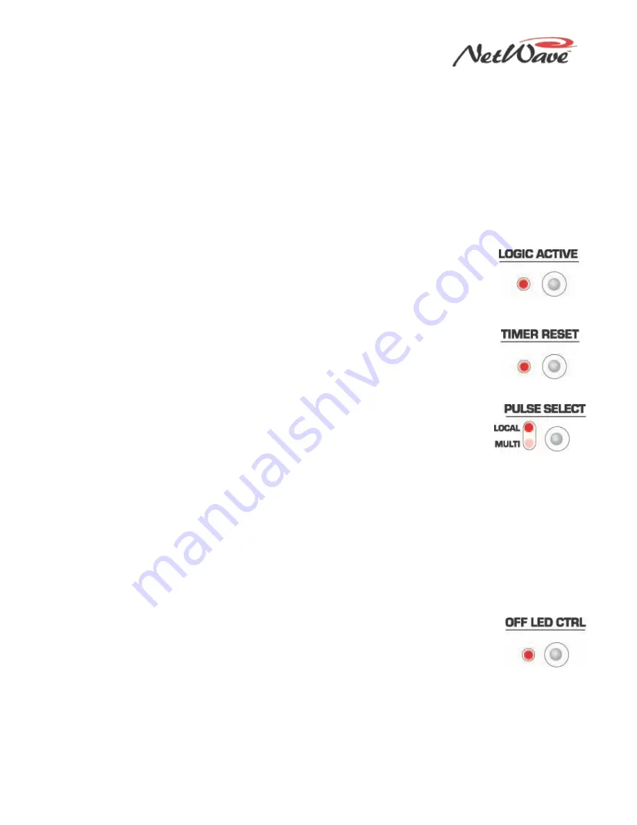
Logic Active — Press this button to turn the LED on or off. When the LED is on, the
channel’s logic I/O connector is active when that source is the selected source on the
fader channel. When the LED is unlit, the logic connector is not associated with the
active source. Do not set Logic Active on both the A and B sources, as it may result
in incorrect logic behavior.
●
Timer Reset — Press this button to turn the Timer Reset function on or off. When the
LED is lit, the channel source sends a timer reset command to the Event Timer at
channel on. When the LED is unlit, no timer reset command is issued for that source.
The Event Timer’s Auto button on the Monitor Control panel must be lit for the channel
timer reset commands to reach the Event Timer.
●
Pulse Select — This button affects how start and stop pulses are generated by Line
or Telco devices. This button is locked out when the special operating mode Tally
Output (Option 2) is active.
•
Both LEDs off – In this default setting, one start and one stop pulse is generated
whenever the channel’s On/Off state changes, which occurs when you press the channel On and Off
buttons or when it receives remote logic on and off commands.
•
Local On and Multi Off – A start or stop pulse is only generated when the channel status is changed
by pressing the fader channel’s On and Off buttons. No start or stop pulse is generated when the
channel is remotely controlled.
•
Local Off and Multi On – A start pulse is generated each time you press the fader channel’s On
button or the channel receives a start command. Likewise, a stop pulse is generated each time you
press the fader channel’s Off button or the channel receives a channel off command. No channel
state change is required to generate additional start or stop pulses.
•
Both Local and Multi LEDs On – A start pulse is generated each time you press the fader channel’s
On button, and a stop pulse is generated every time you press the fader channel’s Off button.
Remote channel on/off commands do not generate any pulses.
●
Off LED Ctrl (Control) —When the LED is unlit—the standard setting—the fader
channel’s Off button is lit while the channel is off. When this LED is lit, the channel’s Off
button lighting is controlled by the remote logic command Ready. This setting is
typically lit for CD players and other peripheral devices that can control the channel’s
off button LED to indicate device status.
If the peripheral is not ready (for example, if no CD is loaded), the channel’s Off button is unlit. When
the peripheral is ready (for example, a CD is loaded and a track is cued), the channel’s Off button is lit
solid. After the peripheral finishes (for example, the CD track has played), the channel’s Off button winks
to indicate the event has completed.


