


-S3 -123
18-2m
OTHER SETTINGS
18_2m W601
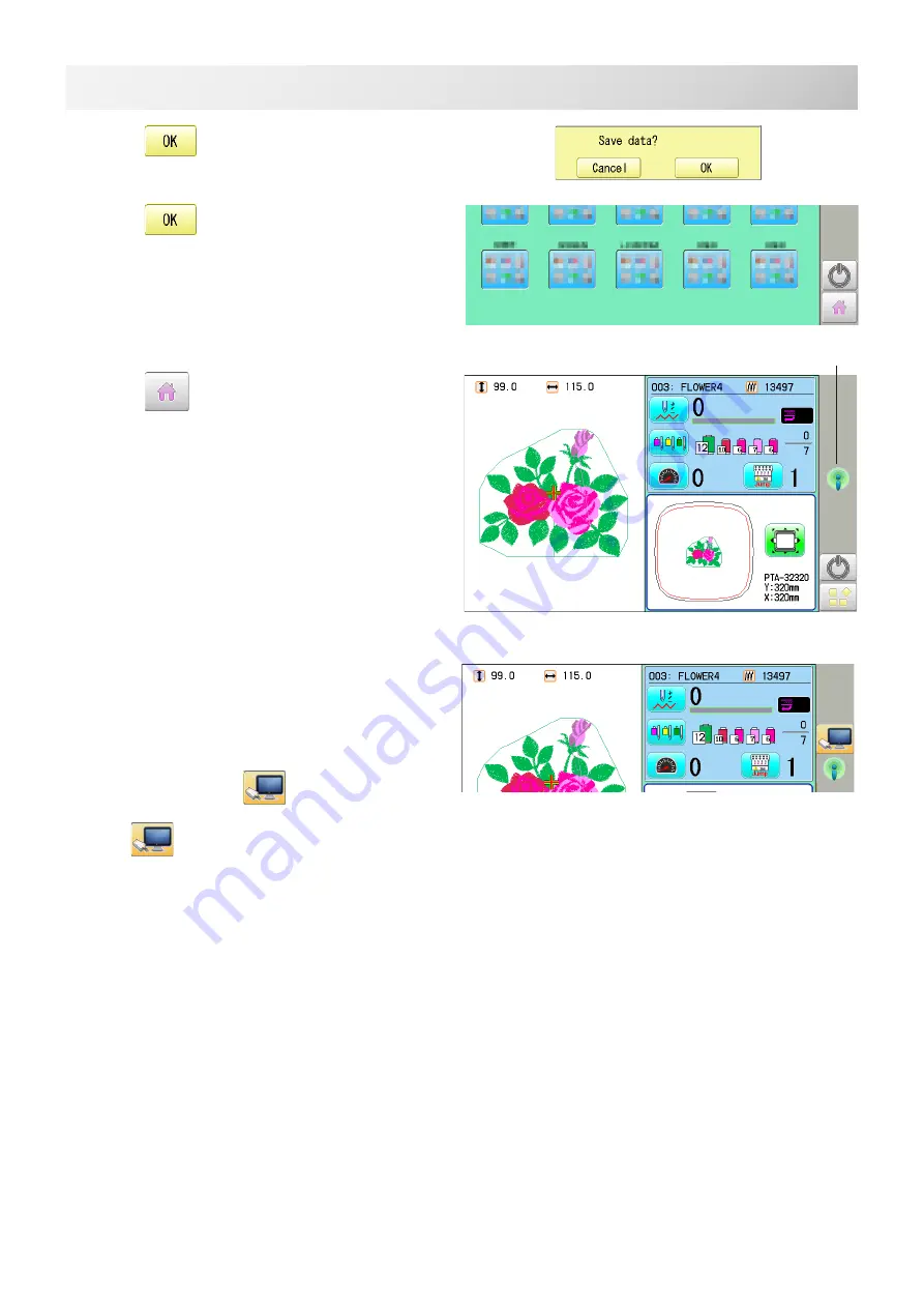
12. Press
.
13. Press
14. Press
.
Wireless connection indicator is displayed if
wireless connection is set up correctly.
If wireless connection indicator is not displayed.
Check wireless connection settings.
The machine is automatically connected
with “HAPPY link LAN” booted on the PC.
If the IP address is set automatically, it will take
longer time to connect than the manual setting.
When connected,
is displayed.
If
is not displayed in the screen, refer to
the next page causes and countermeasures.
Wireless LAN indicator
Summary of Contents for HCU2
Page 1: ...Industrial Single head Embroidery Machine INSTRUCTION BOOK Program Ver C3 06 HCU2 U2W831 1...
Page 2: ......
Page 150: ...D2 117 13 6 FRAME CONFIRMATION 20_5 NB01 11 Press Press to return to Drive mode...
Page 289: ...RA 110 26 3 BUILT IN FONT LIST 26_3 P401 Basic script Diacritic script...
Page 290: ...RA 111 26 3a BUILT IN FONT LIST 26_3a P401...
Page 293: ......
Page 379: ...HCH HCS HCD HCU ONE TOUCH FRAME 7 1 FOPC01 1 12 13 14 2 6 3 B 11 C 9 4 E A 3 4 D C 8 7 5 10...
Page 392: ......


