Chapter 2 Definition and Connection of Interface Signal
365
Ⅲ
C
o
n
n
e
c
tio
n
x1000-gearis selected before modifying the parameter, the system automatically changes into
×100-gear;
②
When SINC is set to 1, MPG/STEP mode ×1000-gear selection is disabled. When x1000-gearis
selected before modifying the parameter, the system automatically changes into ×100-gear;
③
When the external MPG, its axis selection does not lock, that is, the axis selection of MPG is
disabled, the system changes to the non-axis selection state.
④
When the external MPG axis selection and gear selection input are enabled, the axis selection
on the panel and the gear selection keys are disabled; when the external MPG axis selection and
gear selection input are disabled, the axis selection on the panel and the gear selection keys are
enabled and self-locked.
2.8.22 Tri-color Lamp
z
Relevant signals and function definition (standard PLC program)
Signal
type
Symbol
Signal
interface
Address Function
Output
signal
CLPY CN62.31 Y2.2
Yellow— normal state (non-running,
non-alarm state)
CLPG CN62.32 Y2.3
Green—running
state
CLPR CN62.33 Y2.4
Red—alarm
state
2.8.23 Gear/tool number display (only applied to 980TDc-V)
z
Signal diagnosis
Y0025
BIT7
BIT6
BIT5
BIT4
BIT3
BIT2
BIT1
BIT0
Corresponding
BCD code
LED1
2
3
LED1
2
2
LED1
2
1
LED1
2
0
LED0
2
3
LED0
2
2
LED0
2
1
LED0
2
0
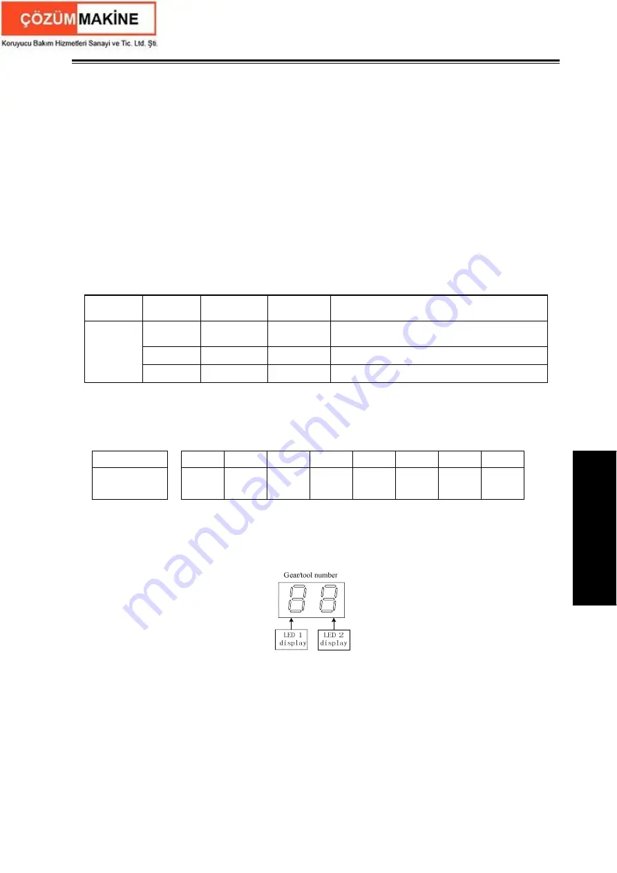
LED 0 displays the current tool number, BIT0~BIT3 of PLC diagnosis number Y25 are BCD code
of the current tool number; LED 1 displays the gear of the current spindle, BIT4~BIT7 of PLC
diagnosis number Y25 are BCD code of the current spindle gear and is shown below:
z
Function description
①
When the tool count is less than 10, the gear and the tool number separately use one LED to
display.
②
When the tool count is more than 10, LED 1 displays 10-digit numbers and the LED 0
displays the single digits.
③
When the gear and the tool number are displayed in time-division, that is, the gear instead of
the tool number is firstly display, the tool number instead of the gear is displayed after 1.5S, and the
system executes them like the above cycle.
Summary of Contents for GSK980TDc
Page 17: ...I Programming ...
Page 18: ...GSK980TDc Turning CNC System User Manual ...
Page 190: ...GSK980TDc Turning CNC System User Manual 172 Ⅰ Programming ...
Page 191: ...Ⅱ Operation Ⅱ Operation ...
Page 192: ...GSK980TDc Turning CNC System User Manua Ⅱ Operation ...
Page 326: ...GSK980TDc Turning CNC System User Manual 306 Ⅱ Operation ...
Page 327: ...Ⅲ Connection Ⅲ Connection ...
Page 328: ...GSK980TDc Turning CNC System User Manual Ⅲ Connection ...
Page 470: ...GSK980TDc Turning CNC System User Manual 448 Ⅲ Connection ...


