Contents
153
Ⅰ
Progra
mming
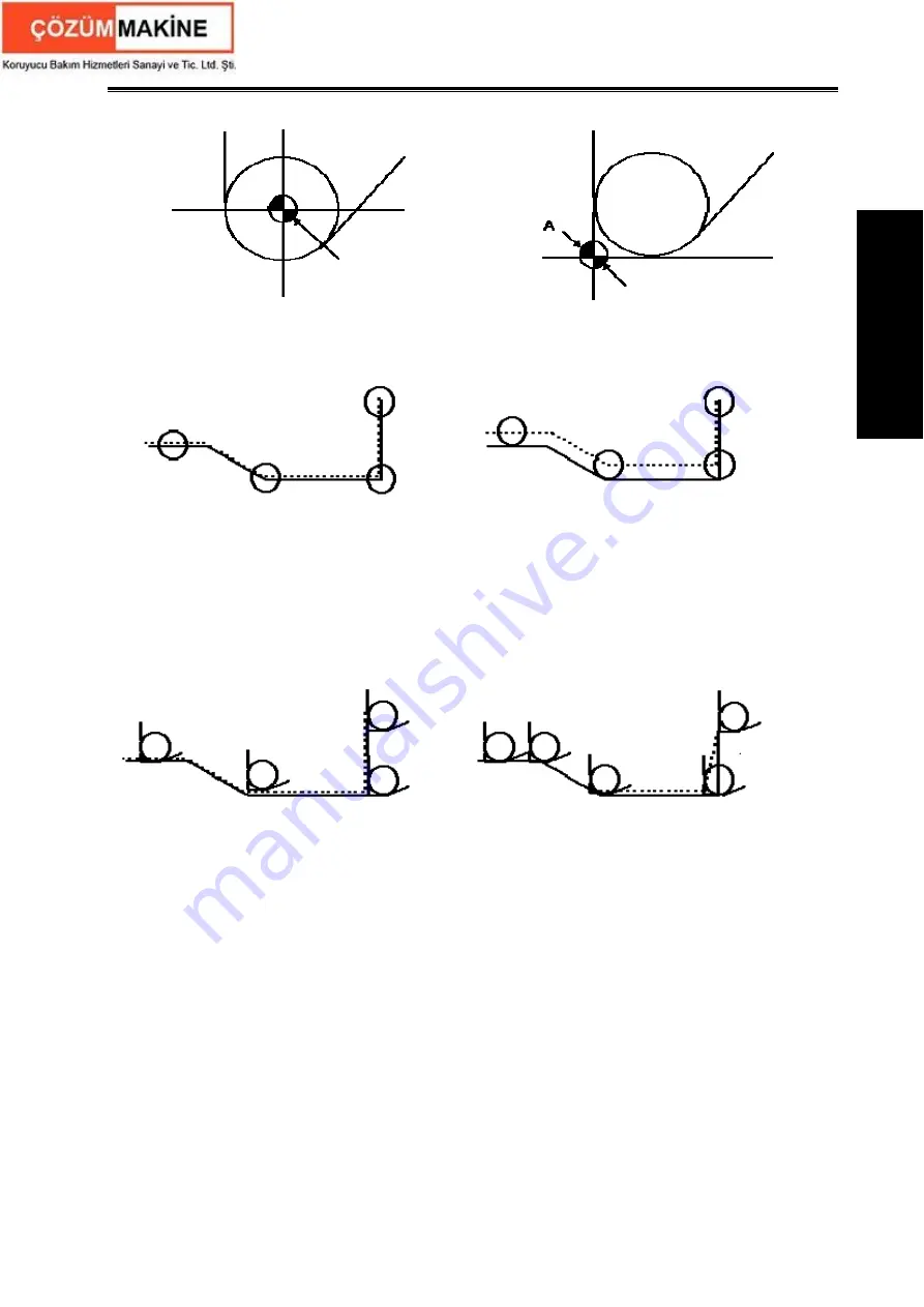
Tool path is shown in Fig.4-5 when the tool nose center programming is executed.
Fig. 4-5-1 the tool nose center path is Fig. 4-5-2 precise cutting with tool
the same that of programmed path without radius compensation
tool radius compensation
The tool path is shown in Fig. 4-6 when imaginary tool nose programming is executed
Fig. 4-6-1 the imaginary tool nose path is Fig. 4-5-2 precise cutting with tool
the same that of programmed path without radius compensation
tool radius compensation
The tool is supposed to one point in programming but the actual cutting blade is not one ideal
point owing to machining technology. Because the cutting blade is not one point but one circular,
machining error is caused which can be deleted by tool nose circular radius compensation. In actual
machining, suppose that there are different position relationship between tool nose point and tool
nose circular center point, and so it must create correct its direction of imaginary tool nose.
From tool nose center to imaginary tool nose, set imaginary tool nose numbers according to tool
direction in cutting. Suppose there are 10 kinds of tool nose setting and 9 directions for position
relationship. The tool nose directions are different in different coordinate system (rear tool post
coordinate system and front tool post coordinate system) even if they are the same tool nose
direction numbers as the following figures. In figures, it represents relationships between tool nose
and starting point, and end point of arrowhead is the imaginary tool nose; T1
~
T8 in rear tool post
coordinate system is as Fig. 4-7; T1
~
T8 in front tool post coordinate system is as Fig. 4-8. The tool
Starting point
Starting point
Fig. 4-3 Programming with tool nose
Fig. 4-4 Programming with imaginary tool nose
Programmed path
Programmed path
Tool nose
center path
Tool nose
center path
Start compensatio
n
Programmed path
Imaginary tool nose
path
Programmed path
Imaginary tool nose
path
Start compensation
Summary of Contents for GSK980TDc
Page 17: ...I Programming ...
Page 18: ...GSK980TDc Turning CNC System User Manual ...
Page 190: ...GSK980TDc Turning CNC System User Manual 172 Ⅰ Programming ...
Page 191: ...Ⅱ Operation Ⅱ Operation ...
Page 192: ...GSK980TDc Turning CNC System User Manua Ⅱ Operation ...
Page 326: ...GSK980TDc Turning CNC System User Manual 306 Ⅱ Operation ...
Page 327: ...Ⅲ Connection Ⅲ Connection ...
Page 328: ...GSK980TDc Turning CNC System User Manual Ⅲ Connection ...
Page 470: ...GSK980TDc Turning CNC System User Manual 448 Ⅲ Connection ...


