GSK980TDc Turning CNC System User Manual
8
Ⅰ
Progra
mming
point is the No.120/No.121 value. Machine zero return/G28 zero return is to execute the machine
reference point return. After the machine zero return/machine reference point return is completed,
GSK980TDc machine coordinate system which takes No.120 value as the reference point, which is
referred to I Programming, Section 3.13.
Note: Do not execute the machine reference point return without the reference point switch installed on the
machine tool, otherwise, the motion exceeds the travel limit and the machine to be damaged.
1.3.3 Workpiece coordinate system and Program Zero
The workpiece coordinate system is a rectangular coordinate system based on the part drawing,
also called floating coordinate system. After the workpiece is installed on the machine, the absolute
coordinates of tool’s current position is set by G50 according to the workpiece’s measure, and so the
workpiece coordinate system is established in CNC. Generally, Z axis of the workpiece coordinate
system coincides with the spindle axis. The established workpiece is valid till it is replaced by a new
one. The system can set 6 workpiece coordinate systems G54~G59 in advance. Refer to I
Programming, Section 3.18 about the details of workpiece coordinate system.
A sub workpiece coordinate system is created in a workpiece coordinate system, which is called
as a local coordinate system. Refer to I Programming, Section 3.17 about the details of the local
coordinate system.
The current position of workpiece coordinate system set by G50 is the program zero.
Note: Do not execute the machine reference point return without using G50 to set the workpiece coordinate
system after power on, otherwise, the alarm occurs.
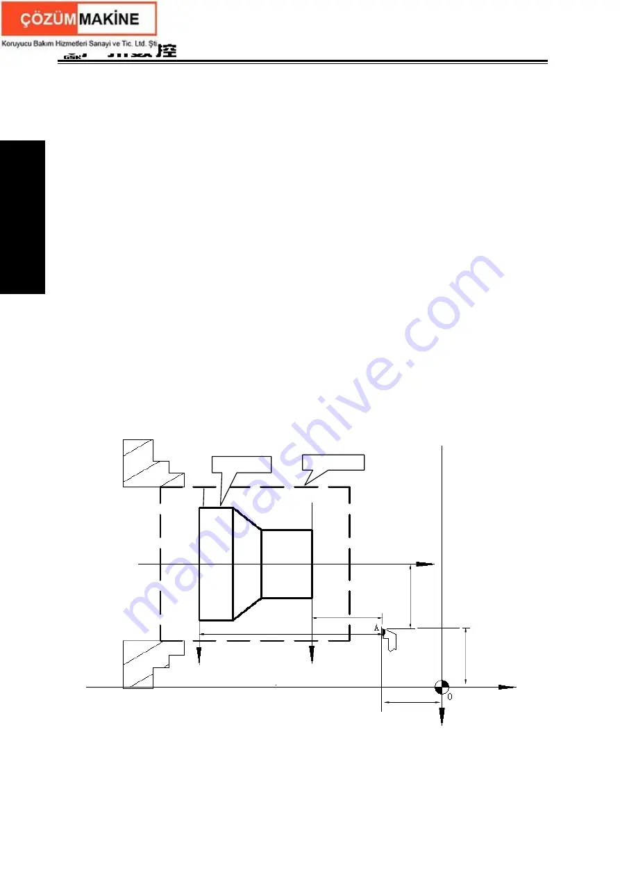
In the above figure, XOZ is the coordinate system of machine tool, X
1
O
1
Z
1
is the workpiece
coordinate system of X axis located at the heading of workpiece, X
2
O
2
Z
2
is the one of X axis located
at the ending of workpiece, O point is the machine reference point, A point is the tool nose and
Fig. 1-6
(x,z)
(x
1
,z
1
)
(x
2
,z
2
)
O
2
O
1
Z
1
(Z
2
)
X
2
X
1
z
2
z
1
x
1
/2
(x
2
/2
)
X
/2
Z
Rod
Workpiece
(0,0)
X
Z
Summary of Contents for GSK980TDc
Page 17: ...I Programming ...
Page 18: ...GSK980TDc Turning CNC System User Manual ...
Page 190: ...GSK980TDc Turning CNC System User Manual 172 Ⅰ Programming ...
Page 191: ...Ⅱ Operation Ⅱ Operation ...
Page 192: ...GSK980TDc Turning CNC System User Manua Ⅱ Operation ...
Page 326: ...GSK980TDc Turning CNC System User Manual 306 Ⅱ Operation ...
Page 327: ...Ⅲ Connection Ⅲ Connection ...
Page 328: ...GSK980TDc Turning CNC System User Manual Ⅲ Connection ...
Page 470: ...GSK980TDc Turning CNC System User Manual 448 Ⅲ Connection ...


