Chapter 2 Definition and Connection of Interface Signal
327
Ⅲ
C
o
n
n
e
c
tio
n
·
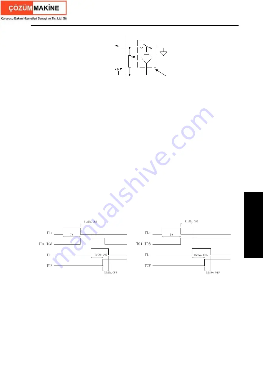
Fig. 2-37
z
Function description (defined by standard PLC program)
The control sequence and control logic of the tool change are defined by PLC program. There
are 4 tool change modes defined as follows by standard PLC program:
1. CHTB (K11.1)=0, CHTA (K11.0)=0: tool change mode B
①
During the tool change process, CNC outputs TL+ signal until the tool in-position signal is
detected, then CNC turns off TL+ signal output and outputs TL- signal after a delay time
specified by data parameter No.082. Then CNC detects TCP signal till it is detected, the CNC
turns off TL- signal after a delay time specified by the data parameter No.085. So the tool change
is over.
②
When CHET(K0011.5) is set to 1(check tool signal after the tool change ends) and the tool
post (CCW) rotation time ends to confirm whether the current tool input signal is consistent with
the current tool No., if not, the system alarms.
③
The tool change process ends.
④
After the system outputs the tool post rotation(CCW)signal, if the CNC doesn’t receive the
TCP signal within the time set by DT08, an alarm will be issued and the TL- signal will be turned
off.
⑤
When the tool post has no tool post locking signal, CTCP(K0011.3) is set to 0, at the time,
the system does not check the tool post locking signal.
or
Sequence of tool change mode B
2. CHTB (K11.1)=0
,
CHTA (K11.0)=1: tool change mode A:
①
After the tool change is executed, the system outputs the tool rotation(CW)signal TL+ and
checks the tool in-position signal, and then after it has checked the tool signal and closes TL+,
last checks whether the tool signal skips, if done, it outputs the tool rotation (CCW) signal TL-.
Then, the system checks the locking signal TCP, it delays the time set by DT09 and closes
TL- after it has received the TCP;
②
When CHET
(
K0011.5
)
is set to 1
(
check tool signal after the tool change ends
)
,
the system
confirms whether the current tool input signal is consistent with the current tool number after the
CNC side
Machine side
Hall switch
Summary of Contents for GSK980TDc
Page 17: ...I Programming ...
Page 18: ...GSK980TDc Turning CNC System User Manual ...
Page 190: ...GSK980TDc Turning CNC System User Manual 172 Ⅰ Programming ...
Page 191: ...Ⅱ Operation Ⅱ Operation ...
Page 192: ...GSK980TDc Turning CNC System User Manua Ⅱ Operation ...
Page 326: ...GSK980TDc Turning CNC System User Manual 306 Ⅱ Operation ...
Page 327: ...Ⅲ Connection Ⅲ Connection ...
Page 328: ...GSK980TDc Turning CNC System User Manual Ⅲ Connection ...
Page 470: ...GSK980TDc Turning CNC System User Manual 448 Ⅲ Connection ...


