5-148
C70 Capacitor Bank Protection and Control System
GE Multilin
5.6 GROUPED ELEMENTS
5 SETTINGS
5
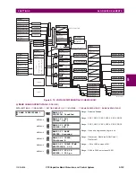
e) NEGATIVE-SEQUENCE OVERVOLTAGE
(ANSI 59_2)
PATH: SETTINGS
ÖØ
GROUPED ELEMENTS
Ö
SETTING GROUP 1(6)
ÖØ
VOLTAGE ELEMENTS
ÖØ
NEG SEQ OV1(3)
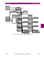
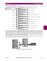
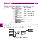
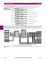
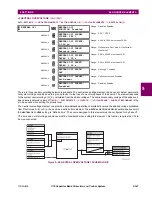
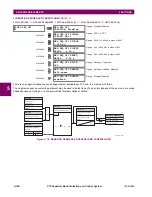
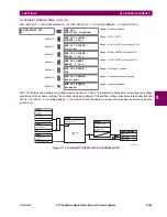
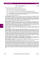
There is one negative-sequence overvoltage element available per CT bank, to a maximum of three.
The negative-sequence overvoltage element may be used to detect loss of one or two phases of the source, a reversed
phase sequence of voltage, or a non-symmetrical system voltage condition.
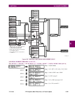
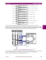
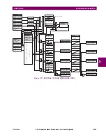
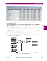
Figure 5–70: NEGATIVE-SEQUENCE OVERVOLTAGE SCHEME LOGIC
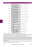
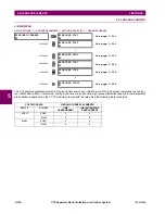
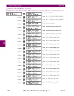
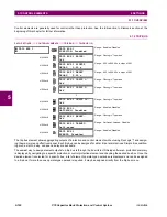
NEG SEQ OV1
NEG SEQ OV1
FUNCTION: Disabled
Range: Disabled, Enabled
MESSAGE
NEG SEQ OV1 SIGNAL
SOURCE: SRC 1
Range: SRC 1, SRC 2
MESSAGE
NEG SEQ OV1 PICKUP:
0.300 pu
Range: 0.000 to 1.250 pu in steps of 0.001
MESSAGE
NEG SEQ OV1 PICKUP
DELAY: 0.50
s
Range: 0.00 to 600.00 s in steps of 0.01
MESSAGE
NEG SEQ OV1 RESET
DELAY: 0.50
s
Range: 0.00 to 600.00 s in steps of 0.01
MESSAGE
NEG SEQ OV1 BLOCK:
Off
Range: FlexLogic™ operand
MESSAGE
NEG SEQ OV1 TARGET:
Self-reset
Range: Self-reset, Latched, Disabled
MESSAGE
NEG SEQ OV1 EVENTS:
Disabled
Range: Disabled, Enabled
SETTING
SETTINGS
FLEXLOGIC OPERANDS
SETTING
SETTING
NEG SEQ OV1
FUNCTION:
NEG SEQ OV1 RESET
DELAY:
NEG SEQ OV1 PICKUP
DELAY:
NEG SEQ OV1 PKP
NEG SEQ OV1 DPO
NEG SEQ OV1 OP
NEG SEQ OV1 BLOCK:
Disabled = 0
Off = 0
Enabled = 1
NEG SEQ OV1 SIGNAL
SOURCE:
Wye VT
Delta VT
V_2
827839A3.CDR
AND
SETTING
NEG SEQ OV1 PICKUP:
V_2 or 3 × V_2
PKP
≥
RUN
t
t
PKP
RST
3 × V_2
Summary of Contents for UR Series C70
Page 2: ......
Page 10: ...x C70 Capacitor Bank Protection and Control System GE Multilin TABLE OF CONTENTS ...
Page 344: ...5 220 C70 Capacitor Bank Protection and Control System GE Multilin 5 10 TESTING 5 SETTINGS 5 ...
Page 586: ...D 10 C70 Capacitor Bank Protection and Control System GE Multilin D 1 OVERVIEW APPENDIXD D ...

