


GE Multilin
C70 Capacitor Bank Protection and Control System
3-3
3 HARDWARE
3.1 DESCRIPTION
3
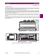
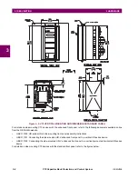
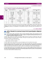
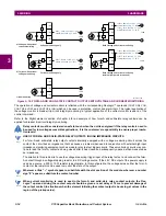
The relay must be mounted such that the faceplate sits semi-flush with the panel or switchgear door, allowing the operator
access to the keypad and the RS232 communications port. The relay is secured to the panel with the use of four screws
supplied with the relay.
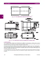
Figure 3–4: C70 VERTICAL DIMENSIONS (ENHANCED PANEL)
14.025”
7.482”
15.000”
4.000”
9.780”
11.015”
1.329”
13.560”
843809A1.CDR
Summary of Contents for UR Series C70
Page 2: ......
Page 10: ...x C70 Capacitor Bank Protection and Control System GE Multilin TABLE OF CONTENTS ...
Page 344: ...5 220 C70 Capacitor Bank Protection and Control System GE Multilin 5 10 TESTING 5 SETTINGS 5 ...
Page 586: ...D 10 C70 Capacitor Bank Protection and Control System GE Multilin D 1 OVERVIEW APPENDIXD D ...


