


GE Multilin
C70 Capacitor Bank Protection and Control System
9-11
9 THEORY OF OPERATION
9.1 OVERVIEW
9
b) BALANCED CASE
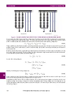
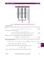
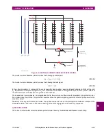
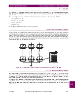
To understand phase current unbalance protection, first note that the currents are driven by the individual admittances in
each string:
(EQ 9.44)
In the above equations,
I
base
represents the differential CT primary current rating. This places the string currents on the
same per-unit base used by the C70. Voltages are expressed in primary volts, capacitances in Farads, and frequency in
radians per second.
The differential current is the vector difference between the two currents:
(EQ 9.45)
The total phase current is the vector sum of the two currents:
(EQ 9.46)
Inserting equation 8.46 into equation 8.45, to eliminate the voltages, we get:
(EQ 9.47)
Inserting this value into equation 8.43, we have:
(EQ 9.48)
The capacitor bank leg-A inherent unbalance factor setting
k
A
is chosen to be:
(EQ 9.49)
As can be seen from the previous two equations, the initial operating signal will be zero.
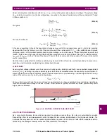
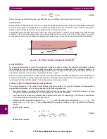
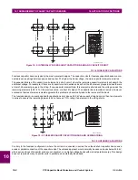
c) SENSITIVITY
Now consider the consequences of an element failure in a typical string, say string A1, making a small capacitance change
in
C
A
1
capacitance. The effect on the operating signal can be calculated by taking the derivative of equation 8.48 with
respect to
C
A
1
.
In the general case, the derivative of the absolute value function is messy, but in our case where the initial value is zero, the
derivative of the absolute function is simply the absolute value of the derivative of its argument. We assume here that
I
A
is
constant, which investigation has shown results in negligible error. The derivative is thus:
I
A
1
j
ω
C
A
1
V
A
V
X
–
(
)
I
base
------------------------------------------
;
I
A
2
j
ω
C
A
2
V
A
V
X
–
(
)
I
base
------------------------------------------
=
=
I
DIF A
( )
I
A
1
I
A
2
–
=
j
ω
V
A
V
X
–
(
)
C
A
1
C
A
2
–
(
)
I
base
---------------------------------------------------------------
=
I
A
I
A
1
I
A
2
+
=
j
ω
V
A
V
X
–
(
)
C
A
1
C
A
2
+
(
)
I
base
---------------------------------------------------------------
=
I
DIF A
( )
I
A
C
A
1
C
A
2
–
C
A
1
C
A
2
+
---------------------------
×
=
I
OP A
( )
I
DIF A
( )
k
A
I
A
–
=
I
A
C
A
1
C
A
2
–
C
A
1
C
A
2
+
---------------------------
×
k
A
I
A
–
=
k
A
C
A
1
C
A
2
–
C
A
1
C
A
2
+
---------------------------
=
Summary of Contents for UR Series C70
Page 2: ......
Page 10: ...x C70 Capacitor Bank Protection and Control System GE Multilin TABLE OF CONTENTS ...
Page 344: ...5 220 C70 Capacitor Bank Protection and Control System GE Multilin 5 10 TESTING 5 SETTINGS 5 ...
Page 586: ...D 10 C70 Capacitor Bank Protection and Control System GE Multilin D 1 OVERVIEW APPENDIXD D ...


