


9-14
C70 Capacitor Bank Protection and Control System
GE Multilin
9.1 OVERVIEW
9 THEORY OF OPERATION
9
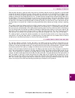
(EQ 9.56)
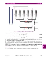
In the above equations,
I
base
represents the differential CT primary current rating, inserted here to put the string currents on
the same per-unit base used by the relay. Voltages are in primary volts, capacitances in Farads, and frequency in radians
per second.
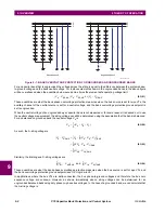
The two neutral currents can be derived from the above equations:
(EQ 9.57)
The differential current is the vector difference between the two currents. By subtracting
I
N
2
from
I
N
1
, one obtains:
(EQ 9.58)
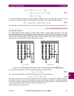
At the same time the total currents in each phase are driven by the total admittance of the two banks in each phase:
(EQ 9.59)
Inserting the equations above into equation 8.58 so as to eliminate the voltages:
(EQ 9.60)
Label
k
A
,
k
B
, and
k
C
as follows:
(EQ 9.61)
Also, convert from phase coordinates into sequence components as follows, and equation 8.60 becomes:
(EQ 9.62)
Substituting this into equation 8.54, we get:
I
A
1
V
A
j
ω
C
A
1
×
I
base
------------------------------
I
A
2
;
V
A
j
ω
C
A
2
×
I
base
------------------------------
=
=
I
B
1
V
B
j
ω
C
B
1
×
I
base
------------------------------
I
B
2
;
V
B
j
ω
C
B
2
×
I
base
------------------------------
=
=
I
C
1
V
C
j
ω
C
C
1
×
I
base
------------------------------
I
C
2
;
V
C
j
ω
C
C
2
×
I
base
------------------------------
=
=
I
N
1
I
A
1
I
B
1
I
C
1
+
+
j
ω
C
A
1
V
A
j
ω
C
B
1
V
B
j
ω
C
C
1
V
C
+
+
I
base
-------------------------------------------------------------------------------------
=
=
I
N
2
I
A
2
I
B
2
I
C
2
+
+
j
ω
C
A
2
V
A
j
ω
C
B
2
V
B
j
ω
C
C
2
V
C
+
+
I
base
-------------------------------------------------------------------------------------
=
=
I
DIF
I
N
1
I
N
2
–
=
j
ω
V
A
C
A
1
C
A
2
–
(
)
V
B
C
B
1
C
B
2
–
(
)
V
C
C
C
1
C
C
2
–
(
)
+
+
[
]
I
base
----------------------------------------------------------------------------------------------------------------------------------------------
=
I
A
I
A
1
I
A
2
+
j
ω
V
A
C
A
1
C
A
2
+
(
)
I
base
---------------------------------------------
=
=
I
B
I
B
1
I
B
2
+
j
ω
V
B
C
B
1
C
B
2
+
(
)
I
base
---------------------------------------------
=
=
I
C
I
C
1
I
C
2
+
j
ω
V
C
C
C
1
C
C
2
+
(
)
I
base
----------------------------------------------
=
=
I
DIF
j
ω
V
A
C
A
1
C
A
2
–
(
)
V
B
C
B
1
C
B
2
–
(
)
V
C
C
C
1
C
C
2
–
(
)
+
+
[
]
I
base
----------------------------------------------------------------------------------------------------------------------------------------------
=
I
A
C
A
1
C
A
2
–
C
A
1
C
A
2
+
---------------------------
I
B
C
B
1
C
B
2
–
C
B
1
C
B
2
+
---------------------------
×
I
C
C
C
1
C
C
2
–
C
C
1
C
C
2
+
---------------------------
×
+
+
×
=
k
A
C
A
1
C
A
2
–
C
A
1
C
A
2
+
---------------------------
k
B
,
C
B
1
C
B
2
–
C
B
1
C
B
2
+
---------------------------
k
C
,
C
C
1
C
C
2
–
C
C
1
C
C
2
+
---------------------------
=
=
=
I
DIF
k
A
I
1
I
2
I
0
+
+
(
)
k
B
a
ˆ
2
I
1
a
ˆ
I
2
I
0
+
+
(
)
k
C
a
ˆ
I
1
a
ˆ
2
I
2
I
0
+
+
(
)
+
+
=
I
1
k
A
a
ˆ
2
k
B
a
ˆ
k
C
+
+
(
)
I
2
k
A
a
ˆ
k
B
a
ˆ
2
k
C
+
+
(
)
I
0
k
A
k
B
k
C
+
+
(
)
+
+
=
Summary of Contents for UR Series C70
Page 2: ......
Page 10: ...x C70 Capacitor Bank Protection and Control System GE Multilin TABLE OF CONTENTS ...
Page 344: ...5 220 C70 Capacitor Bank Protection and Control System GE Multilin 5 10 TESTING 5 SETTINGS 5 ...
Page 586: ...D 10 C70 Capacitor Bank Protection and Control System GE Multilin D 1 OVERVIEW APPENDIXD D ...


