GE Multilin
C70 Capacitor Bank Protection and Control System
9-1
9 THEORY OF OPERATION
9.1 OVERVIEW
9
9 THEORY OF OPERATION 9.1OVERVIEW
9.1.1 GENERAL OPERATION
Static capacitor banks are constructed with a large number of individual capacitor elements connected in a series/parallel
arrangement designed to distribute the system voltage equally among the elements. Equal distribution of voltage is impor-
tant as the rate of internal insulation degradation is a highly non-linear function of element voltage, with degradation accel-
erating very rapidly with overvoltage greater than 10%. To obtain balanced voltages in spite of manufacturing tolerances in
the capacitance of the elements, the elements are positioned in the bank according to their actual capacitance such that
parallel groups have a uniform total capacitance, and a good voltage balance is obtained. However, once in service, individ-
ual elements can fail randomly upsetting the balance, increasing the stress on other elements, and causing their early fail-
ure. Early failure of an element due to unbalanced voltage predictably further unbalances the bank, leading to cascading
failure.
The purpose of capacitor unbalance protection is to detect unbalance caused by element failures as soon as practical, and
to either alarm the condition so that repair can be scheduled for a convenient time, or to automatically remove the bank
from service to prevent deterioration in the healthy elements pending repair. A brut force method would be to directly mea-
sure the voltage across each element, operating on detecting an abnormally high voltage on any element. However, this
approach is seldom economic due to the large number of voltage transducers required. Thus, the C70 supports various
other methods, the suitability of each dependant on the capacitor bank configuration, and on the VTs and CTs available.
The challenge faced by all capacitor unbalance protections not using the brut force method is the increased sensitivity
required due to the less than ideal number of monitoring points, and compensation for the increased effects of inherent
unbalance due to manufacturing tolerance and due to system voltage unbalance.
9.1.2 BANK PHASE OVERVOLTAGE (ANSI 59B)
The capacitor unbalance protection functions discussed in the following sections are intended to detect failures in the
capacitor bank itself that can result in a few capacitor elements being overstressed. However, these unbalance protection
functions do not detect overstressed elements in a healthy bank that can result from external problems. Protection against
overstressing elements from system overvoltages is instead provided by the bank phase overvoltage protection.
Ideally, a bank overvoltage protection should measure the voltage across each capacitor string, allowing an accurate infer-
ence of the voltage across each element in the string, assuming that the string voltage is equally divided across the ele-
ments. This is readily done in grounded wye capacitor banks by simply measuring the three system phase-to-ground
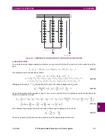
voltages. For instance assuming the bank is healthy, the elements shown in the grounded banks of the figure below will
each be stressed at one-ninth of system phase-to-ground voltage, allowing the inference that the elements are over-
stressed when the system phase-to-ground voltage exceeds nine times the element safe operating voltage limit. The true
RMS value of these phase-to-ground quantities are what the bank phase overvoltage protection measures when the bus
source is set for wye VTs and the bank overvoltage protection ground setpoint is set to grounded.
Summary of Contents for UR Series C70
Page 2: ......
Page 10: ...x C70 Capacitor Bank Protection and Control System GE Multilin TABLE OF CONTENTS ...
Page 344: ...5 220 C70 Capacitor Bank Protection and Control System GE Multilin 5 10 TESTING 5 SETTINGS 5 ...
Page 586: ...D 10 C70 Capacitor Bank Protection and Control System GE Multilin D 1 OVERVIEW APPENDIXD D ...


