


GE Multilin
C70 Capacitor Bank Protection and Control System
5-59
5 SETTINGS
5.2 PRODUCT SETUP
5
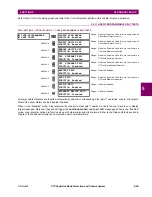
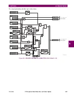
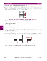
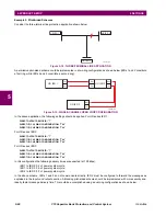
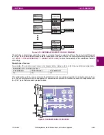
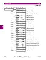
Figure 5–13: INTERLOCKING BUS PROTECTION SCHEME VIA DIRECT INPUTS/OUTPUTS
In the above application, the following settings should be applied. For UR-series IED 1:
DIRECT OUTPUT DEVICE ID:
“1”
DIRECT I/O CH1 RING CONFIGURATION:
“Yes”
DIRECT I/O CH2 RING CONFIGURATION:
“Yes”
For UR-series IED 2:
DIRECT OUTPUT DEVICE ID:
“1”
DIRECT I/O CH1 RING CONFIGURATION:
“Yes”
DIRECT I/O CH2 RING CONFIGURATION:
“Yes”
For UR-series IED 3:
DIRECT OUTPUT DEVICE ID:
“1”
DIRECT I/O CH1 RING CONFIGURATION:
“Yes”
DIRECT I/O CH2 RING CONFIGURATION:
“Yes”
For UR-series IED 4:
DIRECT OUTPUT DEVICE ID:
“1”
DIRECT I/O CH1 RING CONFIGURATION:
“Yes”
DIRECT I/O CH2 RING CONFIGURATION:
“Yes”
Message delivery time is approximately 0.2 of power system cycle (at 128 kbps) times number of ‘bridges’ between the ori-
gin and destination. Dual-ring configuration effectively reduces the maximum ‘communications distance’ by a factor of two.
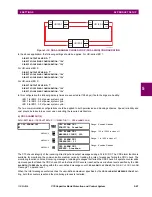
In this configuration the following delivery times are expected (at 128 kbps) if both rings are healthy:
IED 1 to IED 2: 0.2 of power system cycle;
IED 1 to IED 3: 0.4 of power system cycle;
IED 1 to IED 4: 0.2 of power system cycle;
IED 2 to IED 3: 0.2 of power system cycle;
IED 2 to IED 4: 0.4 of power system cycle;
IED 3 to IED 4: 0.2 of power system cycle.
If one ring is broken (say TX2-RX2) the delivery times are as follows:
IED 1 to IED 2: 0.2 of power system cycle;
IED 1 to IED 3: 0.4 of power system cycle;
IED 1 to IED 4: 0.6 of power system cycle;
IED 2 to IED 3: 0.2 of power system cycle;
IED 2 to IED 4: 0.4 of power system cycle;
IED 3 to IED 4: 0.2 of power system cycle.
A coordinating timer for this bus protection scheme could be selected to cover the worst case scenario (0.4 of a power sys-
tem cycle). Upon detecting a broken ring, the coordination time should be adaptively increased to 0.6 of a power system
cycle. The complete application requires addressing a number of issues such as failure of both the communications rings,
failure or out-of-service conditions of one of the relays, etc. Self-monitoring flags of the direct inputs and outputs feature
would be primarily used to address these concerns.
842716A1.CDR
UR IED 1
RX1
TX2
TX1
RX2
UR IED 2
TX2
RX2
RX1
TX1
UR IED 4
TX1
RX1
RX2
TX2
UR IED 3
RX2
TX1
TX2
RX1
Summary of Contents for UR Series C70
Page 2: ......
Page 10: ...x C70 Capacitor Bank Protection and Control System GE Multilin TABLE OF CONTENTS ...
Page 344: ...5 220 C70 Capacitor Bank Protection and Control System GE Multilin 5 10 TESTING 5 SETTINGS 5 ...
Page 586: ...D 10 C70 Capacitor Bank Protection and Control System GE Multilin D 1 OVERVIEW APPENDIXD D ...


