GE Multilin
C70 Capacitor Bank Protection and Control System
6-13
6 ACTUAL VALUES
6.3 METERING
6
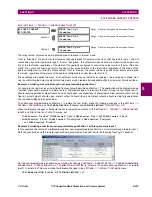
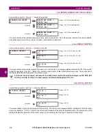
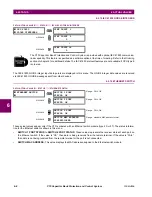
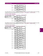
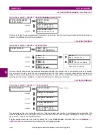
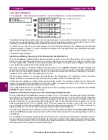
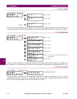
The metered phase current values are displayed in this menu. The "SRC 1" text will be replaced by whatever name was
programmed by the user for the associated source (see
SETTINGS
ÖØ
SYSTEM SETUP
ÖØ
SIGNAL SOURCES
).
c) GROUND CURRENT METERING
PATH: ACTUAL VALUES
ÖØ
METERING
Ö
SOURCE SRC 1
ÖØ
GROUND CURRENT
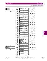
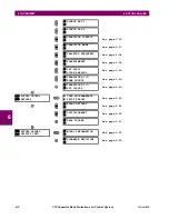
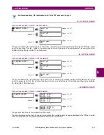
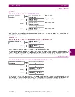
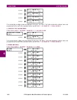
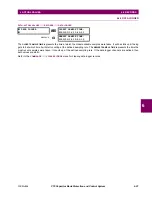
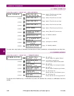
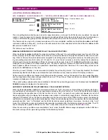
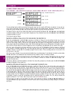
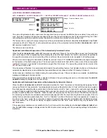
The metered ground current values are displayed in this menu. The "SRC 1" text will be replaced by whatever name was
programmed by the user for the associated source (see
SETTINGS
ÖØ
SYSTEM SETUP
ÖØ
SIGNAL SOURCES
).
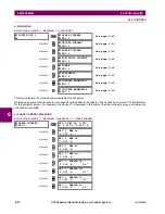
d) PHASE VOLTAGE METERING
PATH: ACTUAL VALUES
ÖØ
METERING
Ö
SOURCE SRC 1
Ö
PHASE VOLTAGE
MESSAGE
SRC 1 ZERO SEQ I0:
0.000 A
0.0°
MESSAGE
SRC 1 POS SEQ I1:
0.000 A
0.0°
MESSAGE
SRC 1 NEG SEQ I2:
0.000 A
0.0°
GROUND CURRENT
SRC 1
SRC 1 RMS Ig:
0.000 A
MESSAGE
SRC 1 PHASOR Ig:
0.000 A
0.0°
MESSAGE
SRC 1 PHASOR Igd:
0.000 A
0.0°
PHASE VOLTAGE
SRC 1
SRC 1 RMS Vag:
0.00 V
MESSAGE
SRC 1 RMS Vbg:
0.00 V
MESSAGE
SRC 1 RMS Vcg:
0.00 V
MESSAGE
SRC 1 PHASOR Vag:
0.000 V
0.0°
MESSAGE
SRC 1 PHASOR Vbg:
0.000 V
0.0°
MESSAGE
SRC 1 PHASOR Vcg:
0.000 V
0.0°
MESSAGE
SRC 1 RMS Vab:
0.00 V
MESSAGE
SRC 1 RMS Vbc:
0.00 V
MESSAGE
SRC 1 RMS Vca:
0.00 V
MESSAGE
SRC 1 PHASOR Vab:
0.000 V
0.0°
MESSAGE
SRC 1 PHASOR Vbc:
0.000 V
0.0°
Summary of Contents for UR Series C70
Page 2: ......
Page 10: ...x C70 Capacitor Bank Protection and Control System GE Multilin TABLE OF CONTENTS ...
Page 344: ...5 220 C70 Capacitor Bank Protection and Control System GE Multilin 5 10 TESTING 5 SETTINGS 5 ...
Page 586: ...D 10 C70 Capacitor Bank Protection and Control System GE Multilin D 1 OVERVIEW APPENDIXD D ...

