422
Upgrade and Maintenance Manual
TX140
S1
System board and components
14.2 USB Flash Module (UFM)
This section provides information on how to install, remove or replace the USB
Flash Module (UFM).
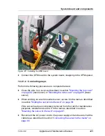
14.2.1 Installing the UFM board
14.2.1.1 Required tools
●
Preliminary and concluding steps: tool-less
●
Installing the UFM:
– Phillips PH1 / (+) No. 1 screw driver
14.2.1.2 Preliminary steps
Before installing the UFM board, perform the following steps:
Ê
Disable BitLocker functionality as described in section
"Disabling BitLocker
functionality" on page 93
.
Ê
Disable boot watchdog functionality as described in section
"Disabling
SVOM boot watchdog functionality" on page 94
.
Ê
If applicable, open the rack door as described in section
"Opening the rack
door" on page 61
.
Ê
Locate the desired server as described in section
"Locating the defective
server" on page 54
.
Ê
Shut down the server as described in section
"Shutting down the server" on
page 61
.
Field Replaceable Units (FRU)
Average hardware task duration: 5 minutes
Average software task duration: 5 minutes
Summary of Contents for PRIMERGY TX140 S1
Page 6: ...Upgrade and Maintenance Manual TX140 S1 ...
Page 22: ...Upgrade and Maintenance Manual TX140 S1 Contents ...
Page 24: ...24 Upgrade and Maintenance Manual TX140 S1 ...
Page 40: ...40 Upgrade and Maintenance Manual TX140 S1 Before you start ...
Page 204: ...204 Upgrade and Maintenance Manual TX140 S1 Hard disk drives solid state drives ...
Page 292: ...292 Upgrade and Maintenance Manual TX140 S1 Expansion cards and backup units ...
Page 306: ...306 Upgrade and Maintenance Manual TX140 S1 Main memory ...
Page 370: ...370 Upgrade and Maintenance Manual TX140 S1 Accessible drives ...
Page 414: ...414 Upgrade and Maintenance Manual TX140 S1 Front panel and external connectors ...
Page 472: ...472 Upgrade and Maintenance Manual TX140 S1 System board and components ...
Page 568: ...568 Upgrade and Maintenance Manual TX140 S1 Cabling ...

