
124
Upgrade and Maintenance Manual
TX140
S1
Power supply
6.1
Standard power supply
6.1.1
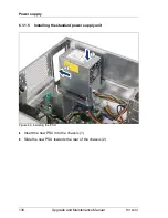
Replacing the standard power supply unit
I
Note for servers using CMA (Cable Management Arm)
Since the installed CMA is blocking PSU modules, additional steps are
required in order to remove or replace PSU modules:
Ê
Unlock the CMA stopper.
Ê
Remove the CMA stopper with the mounted crossbar.
Ê
Support the CMA stopper, the crossbar and the CMA arm including
cables with your right hand.
Ê
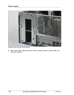
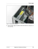
Remove the PSU module and carefully install a new PSU module.
Ê
Remount the complete assembly (CMA stopper, crossbar and CMA
arm) into the rail.
6.1.1.1
Required tools
●
Preliminary and concluding steps: tool-less
●
Replacing the power supply unit:
– Phillips PH2 / (+) No. 2 screw driver
6.1.1.2
Preliminary steps
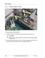
Before replacing the standard power supply unit (PSU), perform the following
steps:
I
You are advised to perform this routine with the server in a horizontal
position.
Ê
Disable BitLocker functionality as described in section
"Disabling BitLocker
functionality" on page 93
.
Field Replaceable Units (FRU)
Average task duration: 10 minutes
Summary of Contents for PRIMERGY TX140 S1
Page 6: ...Upgrade and Maintenance Manual TX140 S1 ...
Page 22: ...Upgrade and Maintenance Manual TX140 S1 Contents ...
Page 24: ...24 Upgrade and Maintenance Manual TX140 S1 ...
Page 40: ...40 Upgrade and Maintenance Manual TX140 S1 Before you start ...
Page 204: ...204 Upgrade and Maintenance Manual TX140 S1 Hard disk drives solid state drives ...
Page 292: ...292 Upgrade and Maintenance Manual TX140 S1 Expansion cards and backup units ...
Page 306: ...306 Upgrade and Maintenance Manual TX140 S1 Main memory ...
Page 370: ...370 Upgrade and Maintenance Manual TX140 S1 Accessible drives ...
Page 414: ...414 Upgrade and Maintenance Manual TX140 S1 Front panel and external connectors ...
Page 472: ...472 Upgrade and Maintenance Manual TX140 S1 System board and components ...
Page 568: ...568 Upgrade and Maintenance Manual TX140 S1 Cabling ...