
TX140 S1
Upgrade and Maintenance Manual
467
System board and components
Ê
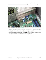
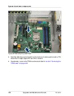
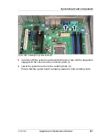
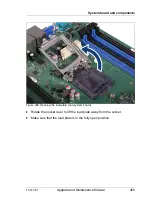
Carefully remove the processor from its socket on the defective system
board as described in
section "Removing the processor" on page 312
.
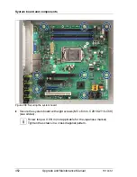
Ê
Install the processor on the new system board as described in
section
"Installing the processor" on page 315
.
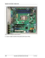
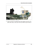
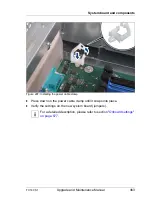
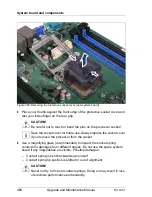
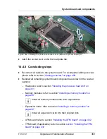
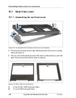
Figure 301: Installing the protective socket cover (defective system board) (A)
I
Since the defective system board is sent back for repair, protect the
delicate processor socket springs with a socket cover.
Ê
Place your thumb against the front edge of the protective socket cover and
rest your index finger on the rear grip.
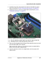
Make sure that the notches on the protective socket cover align with the
posts on the socket (see orange arrows).
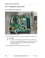
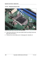
Ê
Lower the protective socket cover straight down onto the socket until it
snaps in place.
Summary of Contents for PRIMERGY TX140 S1
Page 6: ...Upgrade and Maintenance Manual TX140 S1 ...
Page 22: ...Upgrade and Maintenance Manual TX140 S1 Contents ...
Page 24: ...24 Upgrade and Maintenance Manual TX140 S1 ...
Page 40: ...40 Upgrade and Maintenance Manual TX140 S1 Before you start ...
Page 204: ...204 Upgrade and Maintenance Manual TX140 S1 Hard disk drives solid state drives ...
Page 292: ...292 Upgrade and Maintenance Manual TX140 S1 Expansion cards and backup units ...
Page 306: ...306 Upgrade and Maintenance Manual TX140 S1 Main memory ...
Page 370: ...370 Upgrade and Maintenance Manual TX140 S1 Accessible drives ...
Page 414: ...414 Upgrade and Maintenance Manual TX140 S1 Front panel and external connectors ...
Page 472: ...472 Upgrade and Maintenance Manual TX140 S1 System board and components ...
Page 568: ...568 Upgrade and Maintenance Manual TX140 S1 Cabling ...