TX140 S1
Upgrade and Maintenance Manual
323
Processors
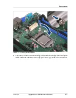
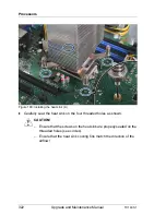
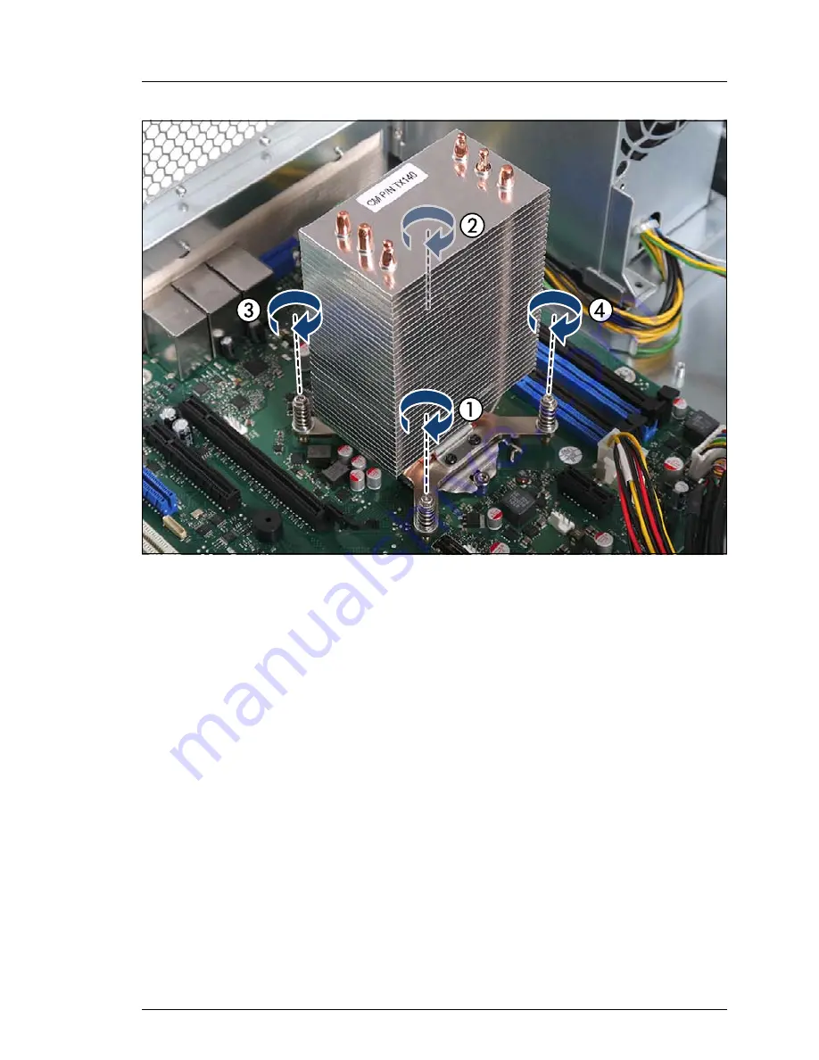
Figure 181: Installing the heat sink (B)
Ê
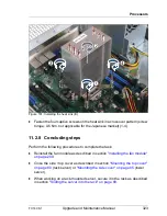
Fasten the four captive screws on the heat sink in a crossover pattern (screw
torque: 0.6 Nm, not applicable for the Japanese market) (1-4).
11.2.8 Concluding steps
Perform the following procedures to complete the task:
Ê
Reinstall the fan module as described in section
"Installing the fan module"
on page 209
.
Ê
Close the side / top cover as described in section
"Mounting the top cover"
on page 80
(rack server) or
"Mounting the side cover" on page 85
(tower
server).
Ê
When working on a rack-mounted server, secure it in the rack as described
in section
"Sliding the server into the rack" on page 89
.
Summary of Contents for PRIMERGY TX140 S1
Page 6: ...Upgrade and Maintenance Manual TX140 S1 ...
Page 22: ...Upgrade and Maintenance Manual TX140 S1 Contents ...
Page 24: ...24 Upgrade and Maintenance Manual TX140 S1 ...
Page 40: ...40 Upgrade and Maintenance Manual TX140 S1 Before you start ...
Page 204: ...204 Upgrade and Maintenance Manual TX140 S1 Hard disk drives solid state drives ...
Page 292: ...292 Upgrade and Maintenance Manual TX140 S1 Expansion cards and backup units ...
Page 306: ...306 Upgrade and Maintenance Manual TX140 S1 Main memory ...
Page 370: ...370 Upgrade and Maintenance Manual TX140 S1 Accessible drives ...
Page 414: ...414 Upgrade and Maintenance Manual TX140 S1 Front panel and external connectors ...
Page 472: ...472 Upgrade and Maintenance Manual TX140 S1 System board and components ...
Page 568: ...568 Upgrade and Maintenance Manual TX140 S1 Cabling ...

