TX140 S1
Upgrade and Maintenance Manual
371
13
Front panel and external
connectors
This chapter provides information on how to replace the front panel module and
optional front LAN connector board.
Safety notes
V
CAUTION!
●
When inserting the front panel module into the server, ensure not to
pinch or strain any connected cables.
●
Circuit boards and soldered parts of internal options are exposed and
can be damaged by static electricity. Always discharge static build-up
(e.g. by touching a grounded object) before handling electrostatic-
sensitive devices (ESDs)
●
Do not touch the circuitry on boards or soldered parts. Hold circuit
boards by their metallic areas or edges.
●
For further information, please refer to chapter
"Important
information" on page 41
.
In this chapter
●
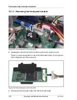
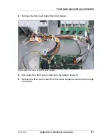
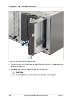
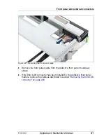
"Replacing the front panel module" on page 372
●
"Installing the front LAN connector" on page 383
●
"Removing the front LAN connector" on page 399
●
"Replacing the front LAN connector and board" on page 408
Summary of Contents for PRIMERGY TX140 S1
Page 6: ...Upgrade and Maintenance Manual TX140 S1 ...
Page 22: ...Upgrade and Maintenance Manual TX140 S1 Contents ...
Page 24: ...24 Upgrade and Maintenance Manual TX140 S1 ...
Page 40: ...40 Upgrade and Maintenance Manual TX140 S1 Before you start ...
Page 204: ...204 Upgrade and Maintenance Manual TX140 S1 Hard disk drives solid state drives ...
Page 292: ...292 Upgrade and Maintenance Manual TX140 S1 Expansion cards and backup units ...
Page 306: ...306 Upgrade and Maintenance Manual TX140 S1 Main memory ...
Page 370: ...370 Upgrade and Maintenance Manual TX140 S1 Accessible drives ...
Page 414: ...414 Upgrade and Maintenance Manual TX140 S1 Front panel and external connectors ...
Page 472: ...472 Upgrade and Maintenance Manual TX140 S1 System board and components ...
Page 568: ...568 Upgrade and Maintenance Manual TX140 S1 Cabling ...

