TX140 S1
Upgrade and Maintenance Manual
119
Basic software procedures
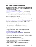
5.2.16 Using the Chassis ID Prom Tool
The Chassis ID EPROM located on a dedicated Chassis ID board or on your
server’s front panel board contains system information like server name and
model, housing type, serial number and manufacturing data.
In order to integrate your system into the ServerView management environment
and to enable server installation using the ServerView Installation Manager,
system data needs to be complete and correct.
After replacing the Chassis ID EPROM, system information has to be entered
using the Chassis ID Prom tool. The tool and further instructions are available
to maintenance personnel from the Fujitsu Technology Solutions Extranet:
https://partners.ts.fujitsu.com/com/service/ps/Servers/PRIMERGY/
Ê
Select your PRIMERGY system from the main area of the page.
Ê
From the categories selection, choose
Software & Tools Documentation
.
Ê
In the
Tools
area click
Tools: Chassis-IDProm Tool
to download the file
(
tool-chassis-Idprom-Tool.zip
).
I
For the Japanese market, follow the instructions provided separately.
The device name that should be selected in the tool is different according
to model line (PYT141***/PYT14P***).
5.2.17 Configuring LAN teaming
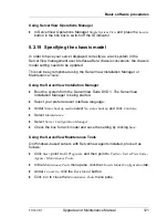
Use ServerView Operations Manager to obtain detailed information on existing
LAN teams:
Ê
In ServerView Operations Manager
Single System View
select
System Status
from the
Information / Operation
menu.
Ê
Under
Network Interfaces
select
LAN Teaming
.
Ê
The
Network Interfaces (Summary)
overview shows all configured LAN teams
and their components. Choose a LAN team to display further details:
–
LAN Team Properties
: Properties of the selected LAN team
–
LAN Team Statistics
: Available statistics about the selected LAN team
I
For more detailed information, refer to the "ServerView Operations
Manager - Server Management" user guide.
Summary of Contents for PRIMERGY TX140 S1
Page 6: ...Upgrade and Maintenance Manual TX140 S1 ...
Page 22: ...Upgrade and Maintenance Manual TX140 S1 Contents ...
Page 24: ...24 Upgrade and Maintenance Manual TX140 S1 ...
Page 40: ...40 Upgrade and Maintenance Manual TX140 S1 Before you start ...
Page 204: ...204 Upgrade and Maintenance Manual TX140 S1 Hard disk drives solid state drives ...
Page 292: ...292 Upgrade and Maintenance Manual TX140 S1 Expansion cards and backup units ...
Page 306: ...306 Upgrade and Maintenance Manual TX140 S1 Main memory ...
Page 370: ...370 Upgrade and Maintenance Manual TX140 S1 Accessible drives ...
Page 414: ...414 Upgrade and Maintenance Manual TX140 S1 Front panel and external connectors ...
Page 472: ...472 Upgrade and Maintenance Manual TX140 S1 System board and components ...
Page 568: ...568 Upgrade and Maintenance Manual TX140 S1 Cabling ...

