54
Upgrade and Maintenance Manual
TX140
S1
Basic hardware procedures
4.1.1
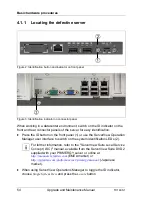
Locating the defective server
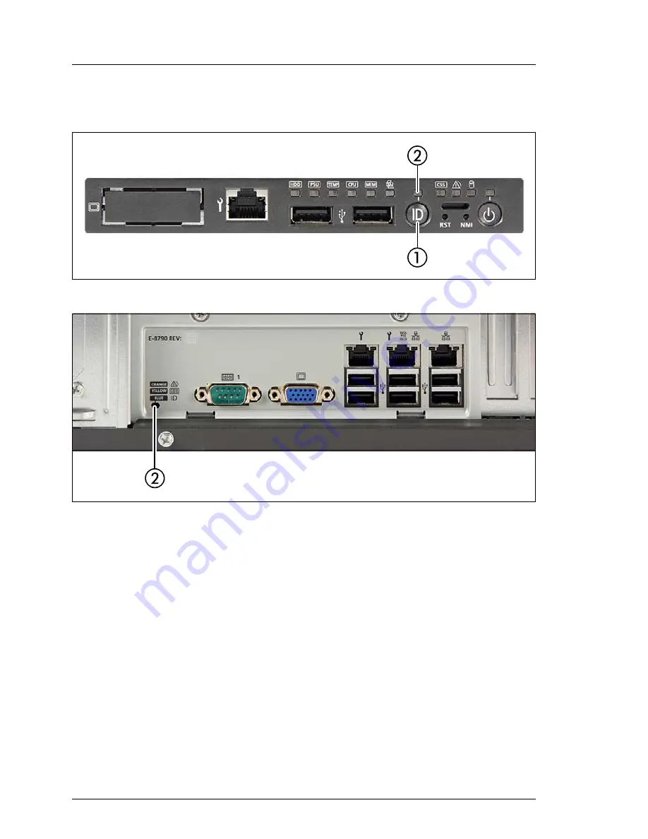
Figure 2: Identification button and indicator on front panel
Figure 3: Identification indicator on connector panel
When working in a datacenter environment, switch on the ID indicator on the
front and rear connector panels of the server for easy identification.
Ê
Press the ID button on the front panel (1) or use the ServerView Operation
Manager user interface to switch on the system identification LEDs (2).
I
For further information, refer to the "ServerView Suite Local Service
Concept (LSC)" manual, available from the ServerView Suite DVD 2
supplied with your PRIMERGY server or online at
http://manuals.ts.fujitsu.com
(EMEA market) or
http://jp.fujitsu.com/platform/server/primergy/manual/
(Japanese
market).
Ê
When using ServerView Operations Manager to toggle the ID indicator,
choose
Single System View
and press the
Locate
button.
Summary of Contents for PRIMERGY TX140 S1
Page 6: ...Upgrade and Maintenance Manual TX140 S1 ...
Page 22: ...Upgrade and Maintenance Manual TX140 S1 Contents ...
Page 24: ...24 Upgrade and Maintenance Manual TX140 S1 ...
Page 40: ...40 Upgrade and Maintenance Manual TX140 S1 Before you start ...
Page 204: ...204 Upgrade and Maintenance Manual TX140 S1 Hard disk drives solid state drives ...
Page 292: ...292 Upgrade and Maintenance Manual TX140 S1 Expansion cards and backup units ...
Page 306: ...306 Upgrade and Maintenance Manual TX140 S1 Main memory ...
Page 370: ...370 Upgrade and Maintenance Manual TX140 S1 Accessible drives ...
Page 414: ...414 Upgrade and Maintenance Manual TX140 S1 Front panel and external connectors ...
Page 472: ...472 Upgrade and Maintenance Manual TX140 S1 System board and components ...
Page 568: ...568 Upgrade and Maintenance Manual TX140 S1 Cabling ...


