
TX140 S1
Upgrade and Maintenance Manual
57
Basic hardware procedures
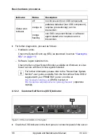
4.1.3
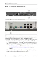
Locating the defective component
After determining the error class by the CSS or Global Error indicators (see
section
4.1.2 on page 55
) local diagnostic indicators on the front panel and
system board allow you to identify the defective component.
I
For further information, refer to the "ServerView Suite Local Service
Concept (LSC)" manual available from the ServerView Suite DVD 2
supplied with your PRIMERGY server or online at
http://manuals.ts.fujitsu.com
(EMEA market) or
http://jp.fujitsu.com/platform/server/primergy/manual/
(Japanese market).
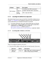
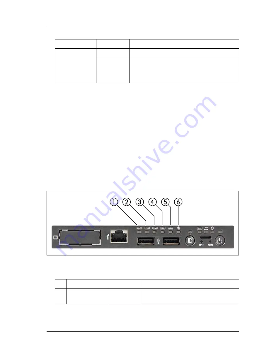
4.1.3.1
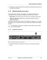
Local diagnostic indicators on the front
Figure 6: Local diagnostic indicators on front panel
Ê
Check the CSS indicator on the front and connector panels of the server:
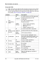
Indicator
Status
Description
CSS indicator
off
no critical event (CSS component)
yellow on
prefailure detected (CSS component)
yellow
flashing
CSS component failure
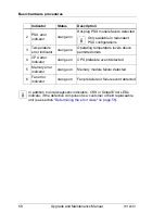
Indicator
Status
Description
1
HDD error
indicator
orange on
HDD / SSD, SAS / SATA backplane or
RAID controller failure detected
Summary of Contents for PRIMERGY TX140 S1
Page 6: ...Upgrade and Maintenance Manual TX140 S1 ...
Page 22: ...Upgrade and Maintenance Manual TX140 S1 Contents ...
Page 24: ...24 Upgrade and Maintenance Manual TX140 S1 ...
Page 40: ...40 Upgrade and Maintenance Manual TX140 S1 Before you start ...
Page 204: ...204 Upgrade and Maintenance Manual TX140 S1 Hard disk drives solid state drives ...
Page 292: ...292 Upgrade and Maintenance Manual TX140 S1 Expansion cards and backup units ...
Page 306: ...306 Upgrade and Maintenance Manual TX140 S1 Main memory ...
Page 370: ...370 Upgrade and Maintenance Manual TX140 S1 Accessible drives ...
Page 414: ...414 Upgrade and Maintenance Manual TX140 S1 Front panel and external connectors ...
Page 472: ...472 Upgrade and Maintenance Manual TX140 S1 System board and components ...
Page 568: ...568 Upgrade and Maintenance Manual TX140 S1 Cabling ...