


5-129
H70
Overload Prevention Control
H70 specifies the decelerating rate of the output frequency to prevent a trip from occurring due to an overload. This control
decreases the output frequency of the inverter before the inverter trips due to a heat sink overheat or inverter overload (with
an alarm indication of
0h1
or
0lu
, respectively). It is useful for equipment such as pumps where a decrease in the output
frequency leads to a decrease in the load and it is necessary to keep the motor running even when the output frequency
drops.
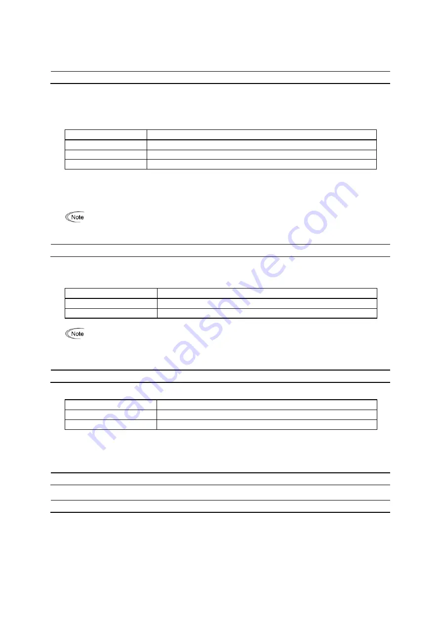
Data for H70
Function
0.00
Decelerate the motor by deceleration time 1 (F08) or 2 (E11)
0.01 to 100.0
Decelerate the motor by deceleration rate from 0.01 to 100.0 (Hz/s)
999
Disable overload prevention control
Overload prevention control --
OLP
(E20 to E24 and E27, data = 36)
This output signal comes ON when the overload prevention control is activated and the output frequency changed.
(Minimum width of the output signal: 100 ms)
In equipment where a decrease in the output frequency does not lead to a decrease in the load, the overload
prevention control is of no use and should not be enabled.
H71 Deceleration
Characteristics
Setting the H71 data to "1" enables forced brake control. If regenerative energy produced during the deceleration of the
motor and returned to the inverter exceeds the inverter’s braking capability, an overvoltage trip will occur. The forced brake
control increases the motor energy loss during deceleration, increasing the deceleration torque.
Data for H71
Function
0 Disable
1 Enable
This function is aimed at controlling the torque during deceleration; it has no effect if there is a braking load.
Enabling the automatic deceleration (anti-regenerative control, H69 = 2 or 4) in the torque limit control mode
disables the deceleration characteristics specified by H71.
H72
Main Power Down Detection (Mode selection)
H72 monitors the inverter alternate-current input power source, and disables the inverter operation if it is not established.
Data for H72
Function
0 Disable
1 Enable
In cases where the power is supplied via a PWM converter or the inverter is connected via the DC link bus, there is no
alternate-current input. In such cases, set H72 data to "0," otherwise the inverter cannot operate.
H73 to H75 Torque Limiter (Operating conditions, Control target, and Target quadrants)
(Refer to F40.)
H76
Torque Limiter (Frequency increment limit for braking)
(Refer to H69.)
Summary of Contents for FRENIC-MEGA
Page 36: ...2 6 Unit inch mm Refer to Section 2 3 3 9...
Page 356: ...MEMO...


