background image


Operating Manual 

SERIES 

P40T-002 

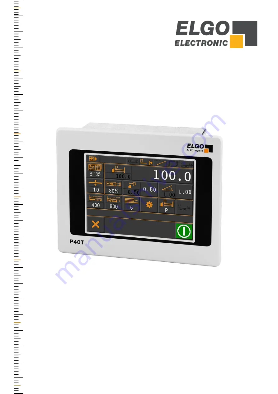
Programmable Touch Screen Controller for 


Guillotine Shears


TFT-Display with touch operation 


Manual inching, single and program mode 


Integrated program memory and auto-cutting machine 


Material depending calculation of gap, angle & pressure  


Sheet support and return to the front function 


Analog inputs and outputs 


Digital outputs up to 2 A 

799000681 / Rev. 7 / 2019-05-13 

Translation of the original operating manual 

Summary of Contents for P40T-002 Series

Page 1: ...ration Manual inching single and program mode Integrated program memory and auto cutting machine Material depending calculation of gap angle pressure Sheet support and return to the front function Analog inputs and outputs Digital outputs up to 2 A 799000681 Rev 7 2019 05 13 Translation of the original operating manual ...

Page 2: ...nz Str 1 D 78239 Rielasingen Worblingen Technical Support 49 0 7731 9339 0 49 0 7731 2 88 03 info elgo de Document No 799000681 Document Name P40T 002 MA E_20 19 Document Revision Rev 7 Issue Date 2019 05 13 Copyright 2019 ELGO Electronic GmbH Co KG ...

Page 3: ...aging Material 9 4 10 Inspection of Transport 9 4 11 Storage 9 5 Product Features 10 6 Technical Data 11 6 1 Identification 11 6 2 Dimensions 11 6 3 Technical Data 12 7 Installation and First Start Up 13 7 1 Operating Area 13 7 2 Mounting of the Controller 14 7 3 Activation of the Device 14 8 Design und Function 15 8 1 Menu Structure 15 9 Main Menu 16 9 1 Language Selection 16 10 Operation Modes 1...

Page 4: ...ections 62 12 1 Connector Arrangement 16 IO Version 62 12 2 Pin Assignment 16 IO Version 63 12 3 Connector Arrangement 8 IO Version 64 12 4 Pin Assignment 8 IO Version 65 13 Parameter Tables 66 13 1 Parameter Setting System 66 13 2 Parameter Times System 66 13 3 Parameter Sub Menu Axes 66 13 4 Parameter Sub Menu Cutting 70 13 5 Parameter Sub Menu Additional Functions 70 13 6 Parameter Sub Menu Sof...

Page 5: ...1 Sub Menu Axis 26 Figure 22 Settings Axis general 27 Figure 23 Axis Distances 32 Figure 24 Creep speed 1 speed 33 Figure 25 Creep speed 2 speeds 34 Figure 26 Creep and Slow speed 3 speeds 34 Figure 27 Axis Times 37 Figure 28 Axis Analog 39 Figure 29 Axis calibration with axis angle 43 Figure 30 Calibration without axis angle 44 Figure 31 Sub Menu Cutting 45 Figure 32 System General 47 Figure 33 S...

Page 6: ...nce Axis Angle 68 Table 12 Parameter list Time axis backgauge 69 Table 13 Parameter list Time axis gap 69 Table 14 Parameter list Time axis angle 69 Table 15 Parameter list Analog axis 70 Table 16 Parameter list Sub Menu cutting 70 Table 17 Parameter list Sub Menu Additional Functions 70 Table 18 Parameter list Sub Menu Soft Keys 71 Table 19 Parameter list Material Table 71 Table 20 Parameter list...

Page 7: ...er to avoid accidents damage and injuries Warning notes DANGER This symbol in connection with the signal word Danger indicates an immediate danger for the life and health of persons Failure to heed these instructions can result in serious damage to health and even fatal injury WARNING This symbol in connection with the word Warning means a possibly impending danger for the life and health of perso...

Page 8: ...device if you have understood the operating manual The operating company is obliged to take appropriate safety measure The initial operation may only be performed by qualified and trained staff Selection and installation of the devices as well as their embedding into the controlling system require qualified knowledge of the applicable laws and normative requirements on the part of the machine manu...

Page 9: ...tions for Transport Unpacking and Loading CAUTION Transport the package box palette etc professionally Do not throw hit or fold it 4 9 Handling of Packaging Material Notes for proper disposal 4 4 4 10 Inspection of Transport Check the delivery immediately after the receipt for completeness and transport damage In case of externally recognizable transport damages Do not accept the delivery or only ...

Page 10: ...gth and cut offset calculation by angle measurement system or time Material list for angle gap and pressure Automatic cutting machine Sheet support Sheet return RTO Serial interface for data exchange with a PC Figure 1 P40T Touch Panel Basic Operation Modes The P40T 002 controller consists of three general operation modes Manual The manual Inching operation allows axis movements via touchscreen Si...

Page 11: ...ce 15 with the corresponding part number Further more the type label contains a unique traceable device number When corresponding with ELGO please al ways indicate this data Figure 2 Type label 6 2 Dimensions Figure 3 Dimensions P40T P40TW 002 024 xx xx CXXX xxxxxxx Consecutive Unit Number Device Desigantion 144 136 180 136 48 Installation depth incl connectors 83 mm Panel cut out 138 x 138 mm Fro...

Page 12: ...rnal inputs 16 digital PNP inputs assignment and logic are freely programmable Input current pin max 10 mA Min pulse time for inputs 300 ms Max input frequency 100 kHz higher on request Analog inputs option 1 3 1 3 analog inputs 12 bit at 3 3 VDC measuring system supply Output signals 16 digital PNP outputs with freely programmable assignment and switching logic active HIGH LOW Output current max ...

Page 13: ... not be installed close to sources of strong inductive or capacitive interference or strong electrostatic fields CAUTION The electrical connections must be made by suitably qualified personnel in accordance with local regulations The device may be designed for switchboard mounting During work on the switchboard all components must be de energized if there is a danger of touching the energized part...

Page 14: ...ews of the mounting brackets attached to the rear panel Turn the two mounting brackets so that the free threaded holes point outwards and then retighten the Phillips screws 3 Now insert the provided grub screws into the threaded holes of the mounting brackets and turn clock wise until the device is firmly seated in the cut out 7 3 Activation of the Device After applying the 24 VDC power supply vol...

Page 15: ...ection is made by touching the corresponding buttons 8 1 Menu Structure Figure 5 Menu Structure 8 1 1 Password NOTE The service mode parameter level is protected by password After login the parameters can be set PIN CODE 250565 Main Menu Manual Service Parameters Single Program Operation Modes ...

Page 16: ... input required 8 1 1 and the clean ing function Figure 6 Start Screen Main Menu 9 1 Language Selection To select the language click on the flag icons at the bottom right see Figure 6 above A mask appears where you can select the desired language by tapping on the corresponding flag symbol Figure 7 Language selection Countdown Cleaning Cleaning Service Parameters Operation Modes Language Selection...

Page 17: ...layed It is also possible to assign a value each for the Cut Length and Cut Offset The material properties can be changed via the material table This is loaded by pressing the material selection key for longer than 5 seconds After releasing the key the material table opens Either the password 2505 for the material table or the service password 250565 is required for access Figure 8 Single Mode Fig...

Page 18: ...isplayed in the Single Mode operating mask for the piece counter 10 1 1 1 10 1 1 2 10 1 1 3 The mode is set resp selected in the piece pre selection window Figure 11 Piece counter selection mask When you exit the single mode or switch off the controller the current quantity is stored in the single block Scroll Exit list Consecutive material number Short Name Plain text field for material descripti...

Page 19: ...te cut until the number 0 is reached Figure 12 Downwards piece counter 10 1 1 2 Upwards Piece Counter The piece counter is incremented after each complete cut A value can be specified at which counting is started Figure 13 Upwards piece counter Counts downwards negative sign Counts upwards positive sign ...

Page 20: ...ing mode the axes can be moved manually Simply activate the corresponding axis and move to the demanded position by using the buttons and The active axis is highlighted in color Figure 15 Manual inching mode Does not count empty field Manual Mode Back gauge Gap 1 left Axis movement in negative direction Angle Cancel Move cutter bar Gap 2 right Axis movement in positive direction ...

Page 21: ...erial table or the service password 250565 is required for access Figure 16 Program Mode and Program List Currently selected Program Program No g consecutive No Number of data sets of the resp program Plain text input field numerical input field will be opened Clear current Program Program Selection Set of Data Active Soft Key Angle Cycle Counter Gap Soft Key Start Backwards Actual Forwards Enter ...

Page 22: ...nter If the program has been executed the cycle counter is decremented and the program jumps back to the beginning If the cycle counter reaches the value 0 the controller is stopped No further cut can be executed The mode can be selected and a value preselected by pressing the cycle counter button The mode is toggled by pressing the cycle counter mode button again Disabled Upwards Downwards Disabl...

Page 23: ...essary material type and thickness or pressure gap and angle applies to the entire program 3 Define a position for backgauge and if necessary a value for cut length and cut offset 4 Switch to next data set 5 Repeat steps 3 and 4 until all desired data sets are defined 6 Finally the end of the program must be defined To do this open the current data set window and activate the E field for End This ...

Page 24: ...he current actual value for this axis 3 MODE 3 positive drive to limit switch with index pulse 10 4 1 Function of a Reference Run The reference run will be started by touching the Reference button for more than 3 seconds The controller now moves the axis to be referenced depending on the parameter Sub Menu Axis Axis General Mode reference 11 4 2 Reference Mode The output reference drive run is set...

Page 25: ...ter touching the service field in the main menu a numerical input field for the password login appears The password 250565 has been assigned as default pin code Figure 20 Password login Sub Menu Axes Sub Menu Cutting Sub Menu Additional Functions PC Interface Material Table Escape Back Save Controller Data Sub Menu Settings System Load Default Parameters Touchscreen Design Pin Assignment Load Cont...

Page 26: ...Service Mode Parameter Level 26 11 3 Sub Menu Axis With this menu all axis parameters can be selected and edited in the corresponding sub level Figure 21 Sub Menu Axis ...

Page 27: ...ode Parameter Level 27 11 4 Settings Axis With this menu the general axis parameter settings of the respective axis can be done Figure 22 Settings Axis general Escape one level back Selection Backgauge Gap Angle ...

Page 28: ...nce run positive with index impulse 11 4 3 Software Endposition Software end positions can be activated or deactivated with this parameter both enabled negative disabled positive enabled both disabled 11 4 4 Decimal Point without 1 10 1 100 1 1000 Backgauge Parameters Gap and Angle Parameters Encoder Analog Dig Disabled Analog Analog Dig Encoder Analog Dig Encoder Digital Analog Analog Dig Encoder...

Page 29: ...st speed forward X X X Creep speed backward X X Slow speed backward X X X Fast speed backward X X X X Drive signals Mode 2 2 speeds Independent outputs forwards and backwards Independent outputs fast and creep speed Output signals 1 2 3 4 Creep speed forward X X Fast speed forward X X Creep speed backward X X Fast speed backward X X Drive signals Mode 3 2 speeds Speed output signals 2 3 Output 4 s...

Page 30: ...backward always fast output 4 sets direction backwards Output signals 1 2 3 4 Creep speed forward X Slow speed forward X X Fast speed forward X X X Creep speed backward X X X X Slow speed backward X X X X Fast speed backward X X X X Drive signals Mode 6 3 speeds Binary coded Output 1 forward Output 4 backward Outputs 2 3 speed Output signals 1 2 3 4 Creep speed forward X X Slow speed forward X X F...

Page 31: ...ection Forced loop with backlash by positioning in positive direction 11 4 7 Hardware Endposition Both enabled Negative disabled Positive enabled Both disabled 11 4 8 Retract Function Mode 1 Retract to actual value adjusted value with return see 11 5 7 Mode 2 Retract to adjusted value with return see 11 5 7 Mode 3 Retract positive to actual value for the adjusted time period with return see 11 6 9...

Page 32: ...ervice Mode Parameter Level 32 11 5 Distances Axis Relevant distance parameters can be set in this menu for the selected axes Figure 23 Axis Distances Escape one level back Selection Backgauge Gap Angle ...

Page 33: ... mm During first start up the stop offset is set first to 0 in order to be able to calibrate the overrun accurately For an exact positioning the stop offset should be as small as possible 0 0 0 2 mm i e the mechanical friction should be steady over the entire retract distance and the slow speed and or creep speed must be accordingly small adjusted The value in register slow speed must be larger th...

Page 34: ...In principle the following applies when setting the speeds Slow speed 20 0 Creep speed 10 0 Correction stop 1 0 Figure 26 Creep and Slow speed 3 speeds Creep speed Correction stop Configuration and Functions Slow speed Creep speed Correction stop Target 100 0 mm Correction stop Slow Middle Fast speed 99 0 mm Creep speed 90 0 mm Slow speed 80 0 mm Fast speed Creep speed Target 100 0 mm Correction s...

Page 35: ...ched from the same direction i e in one direction the target position is exceeded by the value set here After expiration of the backlash dwell time that was entered in register Menu Times Spindle Compensation the axis moves back to the target position 11 5 5 Forced Loop If during absolute positioning the target value is within the range value of the forced loop window a forced loop is run 11 5 6 R...

Page 36: ...measuring unit is set The incoming encoder pulses are multiplied by this factor range 0 00001 to 9 9999 to customize the display to the desired position values Beispiel Encoder 1000 Spindle distance 100 Factor 100 Pulses U mm U Spindle distance mm 100 mm mm 0 1 Pulses 1000 Pulses Pulses ...

Page 37: ...Service Mode Parameter Level 37 11 6 Times Axis Relevant time parameters for the respective axis can be set in this menu Figure 27 Axis Times Escape one level back Selection Backgauge Gap Angle ...

Page 38: ...ls are detected for the duration of the time set here the drive signals are switched off to stop the motor 11 6 5 Delay Contr Start With a start command the start of positioning is delayed by this time 11 6 6 Delay Contr Inpos After a position is reached the output signal is delayed by this time entered in X X sec 11 6 7 Start Delay With a start command the start of positioning is delayed by this ...

Page 39: ...Service Mode Parameter Level 39 11 7 Analog Axis Relevant analog parameters for the respective axis can be set here Figure 28 Axis Analog Escape one level back Selection Backgauge Gap Angle ...

Page 40: ...s U is set in this parameter 11 7 3 Pulse Encoder The number of pulses of the measuring system per revolution of the motor is set here in order to be able to cal culate the nominal speed maximum 9999 pulses per revolution 11 7 4 P Portion Proportional amplification setting range 1 3000 General The P element consists exclusively of a proportional part and thus has an amplifying property The P compo...

Page 41: ...e larger the I component the slower becomes the control loop 11 7 6 D Portion Differential voltage setting range 1 1000 General The D controller differential controller determines the output value from the time derivative of the control devia tion P40T In case of control deviation a short voltage pulse proportional to the rate of change is output in order to com pensate this quickly without perman...

Page 42: ...ssibilities to stop the system the P40T comes with this special register Stop Mode Stop Mode manual mode 0 the voltage of the analog output is set to 0 V 1 the drive is set to a standstill with the greatest possible ramp slope 2 the drive is set to a standstill with the ramp slope according to the Acceleration parameter setting 11 7 15 Start Mode 0 if the axis is in the tolerance zone it is not re...

Page 43: ...Set Increment value inc by Teach field 5 With deactivated axis the according inc values can be readjusted The following machine values are set directly A Distance to measuring system B Distance to pivot point C Blade opening at pivot point D Blade length Figure 29 Axis calibration with axis angle Set Gap Set Angle Note If double gap is deactivated the right column does not appear in the calibratio...

Page 44: ... B Right blade opening at TDC C Minimal blade opening virtual TDC relevant for using with cut offset D If only the backgauge axis is active gap and angle not active and the value is 0 the material thickness is considered as minimal blade opening and the value is not 0 this value is the minimal blade opening E If several axes are activated this value is added to the material thickness F Blade lengt...

Page 45: ...Figure 31 Sub Menu Cutting 11 9 1 Cut Time This parameter defines the time from start of cutting until end of cutting 11 9 2 Offset Cut Time This parameter defines the time from the upper rest position to the start of the cut that the blade needs to lower ...

Page 46: ... after cutting until the knife is lifted back to its rest position 11 9 7 Acc Down This parameter defines the duration between opening the valve and switching ON the pressure when the blade is lowered 11 9 8 Dec Down This parameter defines the duration between switching OFF the pressure and closing the valve when the blade is lowered 11 9 9 Acc Up This parameter defines the duration between openin...

Page 47: ...ng the button pressure active for testing see figure below additionally the setting U at 100 pressure can be activated for testing purposes Figure 32 System General 11 10 1 Pressure Control ON OFF 11 10 2 U at 100 press Here the analog output voltage at 100 pressure can be set Button pressure active for testing off ...

Page 48: ...djust the gap 11 10 5 Gap Angle Pressure locked unlocked hidden 11 10 6 Gap 2 right ON OFF 11 10 7 Next set stepping For program operation various settings can be made for processing the following data set program block without no next set stepping activated without start when a set has been processed the next set is loaded with start when a set has been processed START must be pressed to load the...

Page 49: ...Service Mode Parameter Level 49 11 11Sub Menu Times System Figure 33 System Times ...

Page 50: ...ou can define the time parameter support hold down 11 11 Sub Menu Times Sys tem This is the time that must elapse after the cutter bar has moved up again before the sheet sup port is returned to its initial position 11 11 2 Using Sheet Support in Single and Program Mode 1 Press button Soft Key see also section 10 1 Single Mode 2 Now you can a switch ON OFF a 2 position support b use a 3 position s...

Page 51: ... set again g P40T waits for Input support is down h output support down is reset and time support hold down starts i if blade is in TDC Top Dead Center and time support hold down has elapsed the output support up is set j P40T waits for Input support is up k output support up is reset 11 11 4 Support Delay Runtime until support is active 11 11 5 Support Time Runtime for total support 11 11 6 Suppo...

Page 52: ...to operator Return To Operator 11 12 2 Max Sheet Length RTO Max sheet length for the RTO function push sheet to operator Return To Operator 11 12 3 Min Sheet Thickness RTO Min sheet thickness for the RTO function push sheet to operator Return To Operator 11 12 4 Max Sheet Thickness RTO Max sheet thickness for the RTO function push sheet to operator Return To Operator ...

Page 53: ... is OFF The button changes its color to red to indicate that the pump is running Figure 36 Main Menu pump is ON In manual single or program mode the status of the pump is displayed in the info line above Figure 37 Example Singe Mode pump status in the info line When the pump is switched off the symbol is displayed in black Pump is OFF Pump is ON Pumpe ist AN The pump output is activated by pressin...

Page 54: ...reen In this menu the touch screen can be calibrated Figure 38 Calibration Touch Screen 1 Activate the calibration field 2 Follow the displayed instructions Touch Corner and Hold in the respective corner 3 Finish the calibration process by leaving the mask ...

Page 55: ...ptions can be activated simultaneously If a further option is activated an error message appears Figure 39 Soft Keys Table 2 Soft Keys ON active OFF not active Input Field 1 Conveyor belt 2 Autocut function for operation with foot pedal 3 Backgauge park position 3 1 Enter the park position value for the backgauge 4 Scrap shaft 5 Support 6 RTO Return to Operator 1 2 3 5 6 3 1 4 off ...

Page 56: ...When this function is activated the backgauge is moved to the parking position The corresponding position is entered in the menu Service Soft Keys parkposition The activated function is displayed in color at the soft key Pressing START deactivates the Backgauge park posi tion function and moves the back gauge to the specified target position 11 15 4 Support Sheet Support Activates the soft key She...

Page 57: ...ist Designation of material input designation clear text Switch to material table Set values by touching and input of data If 0 is entered in the sheet thickness column this is recognized as the end of the table and subsequent entries are ignored Figure 40 Material table list Field for entering the selected material as plain text an alphanumeric input field is opened for input Delete the selected ...

Page 58: ...ked in red are fixed in the material table Now a value for the material thickness of 2 5 mm is to be loaded For a better overview only the calculation for the gap value is illustrated in this example The inter mediate steps for the angle are calculated according to the same principle Table 3 Interpolation Procedure Thickness Gap Angle 0 5 0 10 0 75 2 0 0 20 1 00 3 0 0 30 1 25 4 0 0 40 1 50 6 0 0 5...

Page 59: ...connector ST and touching the corresponding HIGH LOW field In addition an output test can be performed see buttons Output test activate deactivate With regard to the output functions it is also possible to activate the pressure and switch the individual outputs ON for test purpos es by touching them Repeated touching changes the status to OFF again Figure 41 Logic assignment of Input Output functi...

Page 60: ...sword see 8 1 1 again Figure 42 Load and save OEM data 11 19Reset to Factory Defaults A reset to the default parameters must be confirmed by entering the password see 8 1 1 again While the data is being loaded the respective button is highlighted in color Figure 43 Load default parameters Load OEM data Save OEM data Load default parameters ...

Page 61: ...sign of the background fields icons text foreground and text back ground In addition the program version and backup ID are displayed important when backing loading via the PC software Backup Tool Figure 44 Touchscreen Design 11 21PC Interface Figure 45 Activate PC interface Customize touchscreen design Activate PC interface ...

Page 62: ...ection diagrams refer to chapter 16 Appendix ST1 ST2 ST7 ST3 ST4 ST5 ST6 ST8 ST9 S12 MCC2 MCC1 Connector No Function ST1 Measuring system connections encoder inputs ST2 Measuring system connections analog inputs ST3 ST4 Digital inputs ST5 ST6 Digital outputs ST7 Analog output 1 PID ST8 Analog output 2 pressure control ST9 24 VDC power supply voltage S12 PC interface adapter cable see 15 1 Accessor...

Page 63: ...ward 3 Drive signal 1 gap1 increase 4 Drive signal 4 gauge backward 4 Drive signal 2 gap1 reduce 5 Drive signal 3 gauge fast 5 Drive signal 1 angle increase 6 Enable control gauge 6 Drive signal 2 angle reduce 7 Support up 7 Drive signal 1 gap2 increase 8 Support down 8 Drive signal 2 gap2 reduce 9 NC 9 Lift blade 10 Conveyor 10 Lower blade ST7 Analog Output optionally PID ST9 Power Supply Voltage...

Page 64: ...ndix ST1 ST2 ST7 ST3 ST4 ST5 ST6 ST8 ST9 S12 MCC2 MCC1 Connector No Function ST1 Measuring system connections encoder inputs ST2 Measuring system connections analog inputs ST3 Digital inputs ST5 Digital outputs ST7 Analog output 1 PID ST8 Analog output 2 pressure control ST9 24 VDC power supply voltage S12 PC interface adapter cable see 15 1 Accessories ...

Page 65: ... forward 4 Drive signal 4 gauge backward 5 Drive signal 1 gap1 increase 6 Drive signal 2 gap1 reduce 7 Support up 8 Support down 9 Lift blade 10 Lower blade ST7 Analog Output optionally PID ST9 Power Supply Voltage 1 0 V GND 1 0 V GND 2 10 VDC 2 24 VDC 10 20 3 PE Earth 3 PE Earth ST8 Analog Output Pressure Control ST12 PC Interface 1 0 V GND 1 GND 2 10 VDC 2 RS232 RX 3 PE Earth 3 RS232 TX NOTE Pin...

Page 66: ... 10 10 Support hold down 0 10 1 0 Delay next set 0 10 0 1 13 3 Parameter Sub Menu Axes Table 6 Parameter list Axis Backgauge Function Setting Range Factory Setting Customer Setting Axis Type IN OUT Encoder Digital Encoder PID Digital Analog Digital Encoder Analog Digital Encoder Analog Digital Encoder Digital Reference mode Mode 1 Mode 2 Mode 3 Mode 3 Software end position both enabled negative di...

Page 67: ...ndle com Mode without with spindle with spindle forced loop forced loop without Retract Mode Mode 1 8 Mode 1 Table 8 Parameter list Setting Angle Function Setting Range Factory Setting Customer Setting Axis Type IN OUT Encoder Digital Encoder PID Digital Analog Digital Encoder Analog Digital Encoder Analog Digital disabled Reference mode Mode 1 Mode 2 Mode 3 Mode 1 Software end position both enabl...

Page 68: ...g Customer Setting Creep speed 0 0 1000 0 5 00 Tolerance window 0 0 100 0 0 02 Spindle compensation 0 0 1000 0 0 10 Reference value 10000 0 100000 0 00 0 End position min 0 05 99999 0 0 05 End position max 0 05 99999 0 5 00 Correction stop forwards 0 0 1000 0 0 02 Manipulation 0 0 100 0 0 02 Forced loop 0 0 1000 0 0 10 Factor 0 000001 1 000000 1 000000 Retract length 0 0 1000 0 0 00 Function Setti...

Page 69: ... Function Setting Range Factory Setting Customer Setting Position reached 0 0 10 0 1 0 Manual change 0 0 10 0 1 0 Delay contr Start 0 0 10 0 0 0 Delay contr Inpos 0 0 10 0 1 0 Start delay 0 0 10 0 0 0 Retract time 0 0 10 0 0 0 Spindle compensation 0 0 10 0 1 0 Monitoring 0 0 10 0 0 0 Shutdown control 0 0 10 0 0 0 Reference time 0 0 10 0 0 0 Function Setting Range Factory Setting Customer Setting P...

Page 70: ...w speed forwards 0 0 10 0 5 0 U U creep speed backwards 0 0 10 0 1 0 U U creep speed 0 0 10 0 1 0 Stop mode general 0 1 2 1 Stop mode manual 0 1 2 1 Stop mode 0 1 1 Function Setting Range Factory Setting Customer Setting Cut time 0 0 10 0 0 5 Offset cut time 0 0 10 0 1 0 Mode cut length over axis angle over time off off Pressure blade up 0 100 40 Time down holder 0 0 10 0 0 5 Blade up delay 0 0 0 ...

Page 71: ...tting Customer Setting Sheet thickness 0 0 40 0 See chapter 11 16 Material Table Gap gap distance end position min gap distance end position max Angle angle distance end position min angle distance end position max Pressure 1 100 Function Setting Range Factory Setting Customer Setting P3 End switch Gauge min HIGH LOW LOW P4 End switch Gauge max HIGH LOW LOW P5 NC HIGH LOW LOW P6 Reference start ga...

Page 72: ...6 Control enable gauge HIGH LOW HIGH P7 Support up HIGH LOW HIGH P8 Support down HIGH LOW HIGH P9 NC HIGH LOW HIGH P10 Conveyor belt HIGH LOW HIGH Function Setting Range Factory Setting Customer Setting P3 Drive signal 1 gap 1 HIGH LOW HIGH P4 Drive signal 2 gap 1 HIGH LOW HIGH P5 Drive signal 1 angle HIGH LOW HIGH P6 Drive signal 2 angle HIGH LOW HIGH P7 Drive signal 1 gap 2 HIGH LOW HIGH P8 Driv...

Page 73: ...ed thorough suitable cable routing The screen of the signal output cable should only be connected to the following circuit on one side The screens should not be grounded on both sides Signal cables always have to be routed separately from the load power line A safety distance of at least 0 5 m has to be kept from inductive and capacitive sources of interference such as con tactors relays motors sw...

Page 74: ...oftware end position minimum angle fell below check parameter or deactivate the corresponding software end posi tion if necessary Software end position minimum gap2 fell below check parameter or deactivate the corresponding software end posi tion if necessary Software end position maximum gauge exceeded check parameter or deactivate the corresponding software end posi tion if necessary Software en...

Page 75: ...erty Therefore Any work to clear the faults may only be performed by sufficiently qualified staff Arrange enough space before starting the works Make sure that the mounting area is clean and tidy Loose components and tools are sources of accidents If components need to be replaced Pay attention to a correct installation of the spare parts Reinstall all the fixing elements properly Before turning o...

Page 76: ...3 analog inputs 3 3 V supply 0 3 3 V 12 Bit 2 Version 002 Version for guillotine shears Options X no further options C screw terminals 8 8 digital inputs 8 digital outputs5 S serial RS232 interface N digital inputs in NPN version XXXX 000 XX Restrictions Analog Output per Axis X no analog output switch off positioning 1 12 bit analog output 10 V PID regulated 4 2 12 bit analog output 10 V unregula...

Page 77: ... VDC out max 600 mA with screw terminals for 2 x 2 5 mm2 wires Dimensions W x H x D 75 x 73 x 114 mm P40 T Interface Cable Art No 820137012 Adapter cable for connecting a P40T to a PC via the RS232 interface Can be used to update the P40T software and to exchange data with the backup tool software RP8 Relay card with 8 change over relays 28 VDC 250 VAC 12 A ...

Page 78: ... gab max Switch endposition gab min I O EA 24VDC I O EA GND 0V Earth 24 VDC GND 0V Outputs ST5 Measuring System Inputs ST1 ST2 1 GND 2 RS232 RX 3 RS232 TX ST8 ST7 ST3 ST9 Inputs Analog Outputs PC Interface GND PE W V U 3 0 2 3 4 5 6 7 8 9 0 2 3 4 5 6 7 8 9 0 2 3 4 5 6 7 8 9 10 4 5 6 7 8 9 10 0 2 3 0 2 3 0 2 3 0 2 3 backward forward 16 Appendix Connection examples ...

Page 79: ...itch endposition gab max Switch endposition gab min I O EA 24VDC I O EA GND 0V Earth 24 VDC GND 0V Outputs ST5 Measuring System Inputs ST1 ST2 1 GND 2 RS232 RX 3 RS232 TX ST8 ST7 ST3 ST9 Inputs Analog Outputs PC Interface GND PE W V U 3 backward 0 2 3 4 5 6 7 8 9 0 2 3 4 5 6 7 8 9 0 2 3 4 5 6 7 8 9 10 4 5 6 7 8 9 10 0 2 3 0 2 3 0 2 3 0 2 3 forward ...

Page 80: ... RS232 RX 3 RS232 TX ST8 ST7 ST3 ST9 Inputs Analog Outputs PC Interface Diodes if necessary see operation manual 0 2 3 4 5 6 7 8 9 0 2 3 4 5 6 7 8 9 0 2 3 4 5 6 7 8 9 10 4 5 6 7 8 9 10 0 2 3 0 2 3 0 2 3 0 2 3 4 5 6 7 8 9 10 ST6 ST4 0 2 3 4 5 6 7 8 9 10 I O EA GND 0V I O EA 24VDC Piece counter Top dead center Bottom dead center Support is up Support is down Start cup foot pedal NC NC GND 0V 24 VDC ...

Page 81: ...ring System Inputs ST1 ST2 1 GND 2 RS232 RX 3 RS232 TX ST8 ST7 ST3 ST9 Inputs Analog Outputs PC Interface GND PE W V U 3 0 2 3 4 5 6 7 8 9 0 2 3 4 5 6 7 8 9 0 2 3 4 5 6 7 8 9 10 4 5 6 7 8 9 10 0 2 3 0 2 3 0 2 3 0 2 3 0 2 3 4 5 6 7 8 9 10 ST6 ST4 0 2 3 4 5 6 7 8 9 10 I O EA GND 0V I O EA 24VDC Piece counter Top dead center Bottom dead center Support is up Support is down Start cup foot pedal NC NC ...

Page 82: ... ST2 1 GND 2 RS232 RX 3 RS232 TX ST8 ST7 ST3 ST9 Eingänge Analog Ausgänge PC Schnittstelle GND PE W V U 3 vor rück 0 2 3 4 5 6 7 8 9 0 2 3 4 5 6 7 8 9 0 2 3 4 5 6 7 8 9 10 4 5 6 7 8 9 10 0 2 3 0 2 3 0 2 3 0 2 3 4 5 6 7 8 9 10 ST6 ST4 0 2 3 4 5 6 7 8 9 10 Ein Aus gang EA GND 0V Ein Aus gang EA 24VDC Stückzähler Oberer Totpunkt Unterer Totpunkt Support ist oben Support ist unten Schitt starten Fußbe...

Page 83: ... 83 Notes ...

Page 84: ... 84 Notes ...

Page 85: ... 85 Notes ...

Page 86: ...60 Lower Blade Time 45 Main Menu 16 Maintenance 73 75 Manipulation 35 Manual Change 38 Manual Fast 41 Manual Mode 20 Manual Slow 41 Material Properties 17 Material Table 57 Menu Structure 15 mm Inch Mode 31 Mode Cut Length 46 Monitoring 38 Mounting of the Controller 14 Next set stepping 48 Operating area 13 Operation Modes 17 Operational safety 7 Order reference 11 Packaging material 9 Parameter L...

Page 87: ...upport Delay 51 Support Holding Time 51 Support Time 51 Technical Data 12 Time Axis 37 Time Down Holder 46 Tolerance Window 35 Touchscreen Design Program Version Backup ID 61 Transport 9 Transport damage 9 Type designation 11 Type Designation 76 U at 100 Pressure 47 v Ref Mode Part 1 41 v Ref Mode Part 2 41 Velocity 40 ...

Page 88: ...me P40T 002 MA E_20 19 Subject to change 2019 ELGO Electronic GmbH Co KG ELGO Electronic GmbH Co KG Measuring Positioning Control Carl Benz Str 1 D 78239 Rielasingen Fon 49 0 7731 9339 0 Fax 49 0 7731 28803 Internet www elgo de Mail info elgo de ...

Reviews: