Operation
IPL350TD-1EN2.pdf
2012-06-18
Milling/Levelling
Milling depth indicator, adjustment
1
2
2
1
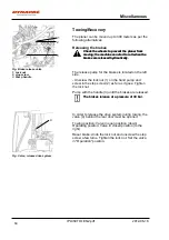
Fig. Milling depth indicator
1. Retaining screw
2. Pointer
There is an adjustable milling depth indicator on each
chassis leg.
The right-hand chassis leg's indicator has a scale for
the position of both sides:
- Chassis leg extended.
- Chassis leg withdrawn.
Let the machine be at level ground:
Lower the spinning milling drum until both sides lightly
scratches the surface.
Adjust the indicator by releasing the retaining screw
(1) and set the pointer (2) to zero. Tighten the
retaining screw.
The stroke length on each chassis leg is shown in
centimeters and optionally in inches.
The stroke length on each chassis leg is shown in
centimeters and optionally in inches.
46
Summary of Contents for PL350 TD
Page 2: ......
Page 16: ...Safety Optional IPL350TD 1EN2 pdf 2012 06 18 8 ...
Page 20: ...Special instructions IPL350TD 1EN2 pdf 2012 06 18 12 ...
Page 66: ...Long term parking IPL350TD 1EN2 pdf 2012 06 18 58 ...
Page 72: ...Preventive maintenance IPL350TD 1EN2 pdf 2012 06 18 64 ...
Page 96: ...Maintenance 250h IPL350TD 1EN2 pdf 2012 06 18 88 ...
Page 106: ...Dynapac Compaction Equipment AB Box 504 SE 371 23 Karlskrona Sweden ...
Page 107: ...Dynapac Compaction Equipment AB Box 504 SE 371 23 Karlskrona Sweden ...


