Miscellaneous
IPL350TD-1EN2.pdf
2012-06-18
1
2
3
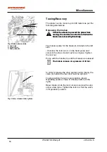
Fig. Brake release valve
1. Lock nut
2. stop screw
3. Pump handle
Towing/Recovery
The planer can be moved up to 300 meters as per the
following alternatives.
Releasing the brakes
Chock the wheels to prevent the planer from
moving; the machine can start to roll when the
brakes are released hydraulically.
Chock the wheels to prevent the planer from
moving; the machine can start to roll when the
brakes are released hydraulically.
The release pump for the brakes is located on the left
side.
- Unscrew the lock nut (1) on the hand pump and
screw in the stop screw (2) as far as it goes. Tighten
the lock nut.
Pump with the handle (3) until the brakes are released.
The brakes release at a pressure of 30 bar.
The brakes release at a pressure of 30 bar.
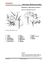
Fig. Valve, release drive system
4
In order to release the drive system during towing, the
valve (4) behind the rear door must be opened:
Towing position: Valve in open position (down)
Operating position: Valve in closed position (to the
right)
Reset brake: Undo the lock nut and unscrew the stop
screw a few turns. Tighten the lock nut. Set the valve
in "Operation" position.
60
Summary of Contents for PL350 TD
Page 2: ......
Page 16: ...Safety Optional IPL350TD 1EN2 pdf 2012 06 18 8 ...
Page 20: ...Special instructions IPL350TD 1EN2 pdf 2012 06 18 12 ...
Page 66: ...Long term parking IPL350TD 1EN2 pdf 2012 06 18 58 ...
Page 72: ...Preventive maintenance IPL350TD 1EN2 pdf 2012 06 18 64 ...
Page 96: ...Maintenance 250h IPL350TD 1EN2 pdf 2012 06 18 88 ...
Page 106: ...Dynapac Compaction Equipment AB Box 504 SE 371 23 Karlskrona Sweden ...
Page 107: ...Dynapac Compaction Equipment AB Box 504 SE 371 23 Karlskrona Sweden ...


