7.
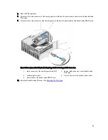
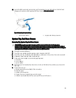
Open the PCIe cage door.
8.
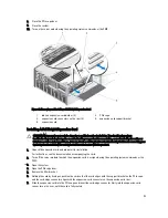
Disconnect the 6-pin connectors of the auxiliary power cable from the power cable connectors on the double-wide
PCIe cage.
9.
Disconnect the 8-pin connector of the auxiliary power cable from the power cable of the double-wide GPGPU card.
Figure 66. Removing and Installing the Auxiliary Power Cable to the Power Cable Connectors
1.
6-pin connector of the auxiliary power cable (2)
2.
power cable connectors on the double-wide
PCIe cage
3.
auxiliary power cable
4.
8-pin connector of the auxiliary power cable
5.
power cable of the double-wide GPGPU card
10. Remove the double-wide PCIe cage. See
Removing The PCIe Cage
.
99
Summary of Contents for PowerEdge M520
Page 1: ...Dell PowerEdge VRTX Enclosure Owner s Manual Regulatory Model E22S Regulatory Type E22S001 ...
Page 8: ...8 ...
Page 34: ...34 ...
Page 66: ...Figure 45 Securing the Power Cable Without Wheel Assembly 1 power cable 2 strap 66 ...
Page 148: ...148 ...
Page 151: ...Figure 94 System Board Connectors Back 1 midplane planar connectors 3 151 ...
Page 152: ...152 ...
Page 158: ...158 ...

