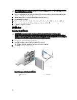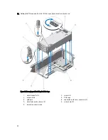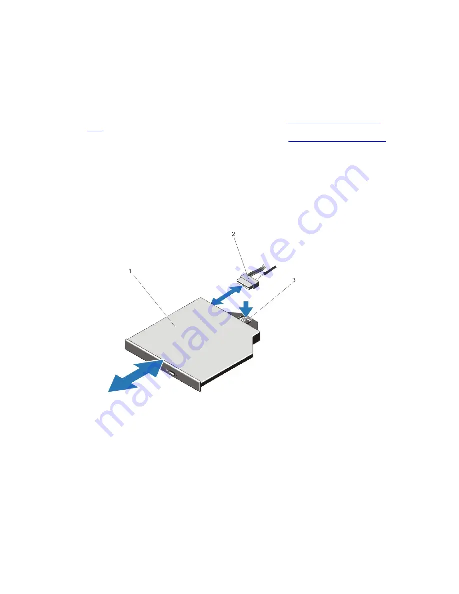
11. Disconnect the power/data cable from the back of the optical drive.
Note the routing of the power/data cable as you remove them from the system board and the optical drive. You
must route these cables properly when you replace them to prevent them from being pinched or crimped.
12. To release the optical drive, press and push the release tab toward the front of the enclosure.
13. Slide the optical drive out of the enclosure until it is free of the optical-drive slot.
14. If you are not adding a new optical drive, install the optical-drive blank.
15. Reinstall the backplane expander board and connect the SAS cables. See
Installing The Backplane Expander
Board
.
For the 3.5 inch hard-drive chassis, reinstall the hard-drive backplane. See
Installing The Hard-Drive Backplane
.
16. Reinstall the cooling-fan assembly.
17. Reinstall the cooling shroud.
18. Close the system.
19. If applicable, place the system upright on a flat, stable surface and rotate the system feet outward.
20. If removed, reinstall the hard drives, server modules, and power supplies.
21. Reconnect the enclosure to its electrical outlet and turn the enclosure on, including any attached peripherals.
22. Turn on the server modules using the operating system commands or the CMC.
23. If applicable, install the front bezel.
Figure 53. Removing and Installing the Optical Drive
1.
optical drive
2.
power/data cable
3.
release tab
78
Summary of Contents for PowerEdge M520
Page 1: ...Dell PowerEdge VRTX Enclosure Owner s Manual Regulatory Model E22S Regulatory Type E22S001 ...
Page 8: ...8 ...
Page 34: ...34 ...
Page 66: ...Figure 45 Securing the Power Cable Without Wheel Assembly 1 power cable 2 strap 66 ...
Page 148: ...148 ...
Page 151: ...Figure 94 System Board Connectors Back 1 midplane planar connectors 3 151 ...
Page 152: ...152 ...
Page 158: ...158 ...


