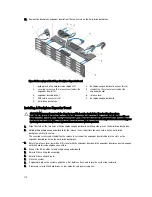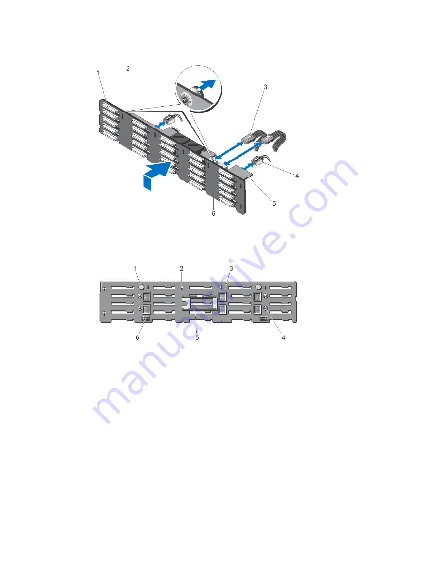
13. Pull the backplane release pins in the direction of the system board and lift the backplane from the chassis.
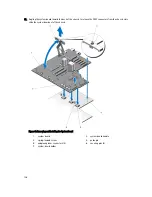
Figure 78. Removing and Installing the 2.5 inch (x25) Hard-drive Backplane
1.
hard-drive connectors (25)
2.
release pins (2)
3.
SAS cables on backplane expander board (2)
4.
power cables (2)
5.
backplane expander board
6.
hard-drive backplane
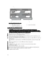
Figure 79. Back View of the 2.5 inch (x25) Hard-drive Backplane
1.
release pins (2)
2.
slots for chassis hooks (10)
3.
backplane expander board connectors (6)
4.
guide pins for the backplane expander boards
(4)
5.
backplane expander board brackets (2)
6.
power cable connectors (2)
120
Summary of Contents for PowerEdge M520
Page 1: ...Dell PowerEdge VRTX Enclosure Owner s Manual Regulatory Model E22S Regulatory Type E22S001 ...
Page 8: ...8 ...
Page 34: ...34 ...
Page 66: ...Figure 45 Securing the Power Cable Without Wheel Assembly 1 power cable 2 strap 66 ...
Page 148: ...148 ...
Page 151: ...Figure 94 System Board Connectors Back 1 midplane planar connectors 3 151 ...
Page 152: ...152 ...
Page 158: ...158 ...


