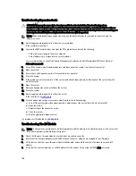
Troubleshooting Expansion Cards
CAUTION: Many repairs may only be done by a certified service technician. You should only perform
troubleshooting and simple repairs as authorized in your product documentation, or as directed by the online or
telephone service and support team. Damage due to servicing that is not authorized by Dell is not covered by your
warranty. Read and follow the safety instructions that came with the product.
NOTE: When troubleshooting an expansion card, see the documentation for your operating system and the
expansion card.
1.
Run the appropriate diagnostic test from the server module.
If the test fails, go to step 3.
2.
Log in to the CMC web interface and view the PCIe properties and verify the following:
– PCIe slots are assigned to the server modules.
– Virtual adapters are assigned to the server modules.
For more information, see the
Dell Chassis Management Controller for Dell PowerEdge VRTX User’s Guide
at
dell.com/esmmanuals.
3.
Turn off the system and attached peripherals, and disconnect the system from the electrical outlet.
4.
Open the system.
5.
Ensure that each expansion card is firmly seated in its connector.
6.
Close the system.
7.
If the problem is not resolved, turn off the system and attached peripherals, and disconnect the system from the
electrical outlet.
8.
Open the system.
9.
Remove all expansion cards installed in the system.
10. Close the system.
11. Run the appropriate diagnostic test from the server.
If the tests fail, see
Getting Help
.
12. For each expansion card you removed in step 9, perform the following steps:
a) Turn off the system and attached peripherals, and disconnect the system from the electrical outlet.
b) Open the system.
c) Reinstall one of the expansion cards.
d) Close the system.
e) Run the appropriate diagnostic test.
If a problem is still indicated, see
Getting Help
.
Troubleshooting The I/O Module
NOTE: To eliminate the possibility of a hardware problem with the module or its attaching devices, first ensure that
the module is properly initialized and configured.
1.
Check that the pass-through module or switch ports are cabled correctly.
2.
Ensure that the network daughter cards/LOM cards on the server modules are mapped to the I/O module.
3.
Verify that the switch or pass-through module is fully booted, and verify the switch’s firmware revision and IP
address.
4.
Verify that the switch module has a valid IP address for the subnet. Verify using the ICMP ping command.
146
Summary of Contents for PowerEdge M520
Page 1: ...Dell PowerEdge VRTX Enclosure Owner s Manual Regulatory Model E22S Regulatory Type E22S001 ...
Page 8: ...8 ...
Page 34: ...34 ...
Page 66: ...Figure 45 Securing the Power Cable Without Wheel Assembly 1 power cable 2 strap 66 ...
Page 148: ...148 ...
Page 151: ...Figure 94 System Board Connectors Back 1 midplane planar connectors 3 151 ...
Page 152: ...152 ...
Page 158: ...158 ...


