5.
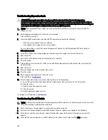
Check the network connector indicators on the network switch module:
– If the link indicator displays an error condition, check all cable connections.
– Try another connector on the external switch or hub.
– If the activity indicator does not light, replace the network switch module.
6.
Using the switch management interface, verify the switch port properties. If the switch is configured correctly,
back up the switch configuration and replace the switch. See the switch module documentation for details.
7.
Ensure that the appropriate Network Daughter Card(s) (NDC) are installed in the server module(s). If the network
link indicator on the server module is green, then the server module has a valid link to the I/O module.
8.
Ensure that the appropriate operating system drivers are installed and that the protocol settings are configured to
ensure proper communication.
147
Summary of Contents for PowerEdge M520
Page 1: ...Dell PowerEdge VRTX Enclosure Owner s Manual Regulatory Model E22S Regulatory Type E22S001 ...
Page 8: ...8 ...
Page 34: ...34 ...
Page 66: ...Figure 45 Securing the Power Cable Without Wheel Assembly 1 power cable 2 strap 66 ...
Page 148: ...148 ...
Page 151: ...Figure 94 System Board Connectors Back 1 midplane planar connectors 3 151 ...
Page 152: ...152 ...
Page 158: ...158 ...


