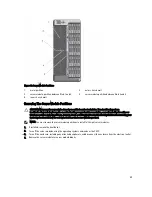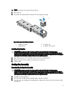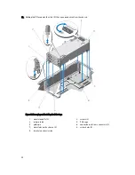
Cooling Fans
Your system supports six hot-swappable cooling fans that provide cooling to the storage and I/O components in the
enclosure.
To provide increased cooling to the storage and PCIe components in the chassis, you can set the fan configuration to
Fan Offset in the CMC web interface.
For more information on the Fan Offset option, see “Advanced Fan Configuration” in the CMC
Online Help
.
NOTE: In the event of a problem with a particular fan, the fan number is referenced by the system’s management
software, allowing you to easily identify and replace the appropriate fan by noting the fan numbers on the cooling
fan assembly.
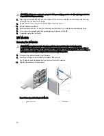
Removing A Cooling Fan
WARNING: Opening or removing the system cover when the system is on may expose you to a risk of electric
shock. Exercise utmost care while removing or installing cooling fans.
WARNING: The cooling fan can continue to spin for some time after it has been powered down. Allow time for the
fan to stop spinning before removing it from the system.
CAUTION: Many repairs may only be done by a certified service technician. You should only perform
troubleshooting and simple repairs as authorized in your product documentation, or as directed by the online or
telephone service and support team. Damage due to servicing that is not authorized by Dell is not covered by your
warranty. Read and follow the safety instructions that came with the product.
CAUTION: To maintain optimum thermal conditions, ensure that there are no obstructions to airflow on the front
and back of the enclosure. The front and back of the enclosure must have at least 30 cm (12 inches) and 61 cm (24
inches) of unobstructed space respectively.
CAUTION: The cooling fans are hot-swappable. To maintain proper cooling while the system is on, replace only
one fan at a time.
70
Summary of Contents for PowerEdge M520
Page 1: ...Dell PowerEdge VRTX Enclosure Owner s Manual Regulatory Model E22S Regulatory Type E22S001 ...
Page 8: ...8 ...
Page 34: ...34 ...
Page 66: ...Figure 45 Securing the Power Cable Without Wheel Assembly 1 power cable 2 strap 66 ...
Page 148: ...148 ...
Page 151: ...Figure 94 System Board Connectors Back 1 midplane planar connectors 3 151 ...
Page 152: ...152 ...
Page 158: ...158 ...


