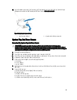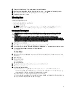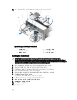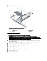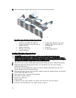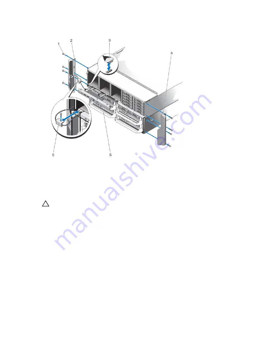
11. Remove the screws securing the mounting ears to the chassis, and remove the mounting ears from the chassis.
Figure 74. Removing and Installing the Mounting Ears
1.
screws (8)
2.
top mounting ear
3.
LCD module cable
4.
bottom mounting ear
5.
control panel
6.
LCD cable holder
Installing The Mounting Ears
CAUTION: Many repairs may only be done by a certified service technician. You should only perform
troubleshooting and simple repairs as authorized in your product documentation, or as directed by the online or
telephone service and support team. Damage due to servicing that is not authorized by Dell is not covered by your
warranty. Read and follow the safety instructions that came with the product.
1.
Align the slots on the mounting ears with the metal tabs on the chassis.
When properly aligned, the screw holes on the mounting ears align with the screw holes on the chassis.
2.
Attach the screws to secure the mounting ears to the chassis.
3.
To install the top mounting ear:
a) Route the LCD cable properly to prevent it from being pinched or crimped.
b) Align the slot on the cable holder with the metal standoff on the chassis, and slide the holder into the chassis.
c) Install the screw to secure the cable holder to the chassis.
d) Reconnect the LCD module cable to the control panel.
e) Slide the control panel into the chassis and install the screws to secure the panel to the chassis.
4.
Reinstall the following:
a) system top cover
b) PCIe cage door
112
Summary of Contents for PowerEdge M520
Page 1: ...Dell PowerEdge VRTX Enclosure Owner s Manual Regulatory Model E22S Regulatory Type E22S001 ...
Page 8: ...8 ...
Page 34: ...34 ...
Page 66: ...Figure 45 Securing the Power Cable Without Wheel Assembly 1 power cable 2 strap 66 ...
Page 148: ...148 ...
Page 151: ...Figure 94 System Board Connectors Back 1 midplane planar connectors 3 151 ...
Page 152: ...152 ...
Page 158: ...158 ...

