6.
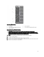
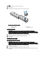
To remove the server module partition between Slots 2 and 4:
a) Hold the release tab on the server module partition and pull it out from the chassis wall to disengage the
locking tab from the chassis slot.
b) Holding the release tab, pull the partition toward the front of the system until it stops sliding.
The tabs on the partition move to unlock position.
c) Rotate the partition downward in the counter-clockwise direction to disengage the tabs from the slots on the
metal partition.
d) Slide the partition out from the system, and save for future use.
Figure 40. Removing and Installing the Server Module Partition Between Slots 2 and 4
1.
metal partition
2.
server module partition
3.
tabs on the server module partition
4.
slots on the inner chassis wall
5.
locking tab on server module partition
6.
inner chassis wall
7.
Install the server modules.
8.
Reconnect the enclosure to the electrical outlet and turn the enclosure on, including any attached peripherals.
9.
Turn on the server modules using the operating system commands or the CMC.
10. If applicable, install the front bezel.
61
Summary of Contents for PowerEdge M520
Page 1: ...Dell PowerEdge VRTX Enclosure Owner s Manual Regulatory Model E22S Regulatory Type E22S001 ...
Page 8: ...8 ...
Page 34: ...34 ...
Page 66: ...Figure 45 Securing the Power Cable Without Wheel Assembly 1 power cable 2 strap 66 ...
Page 148: ...148 ...
Page 151: ...Figure 94 System Board Connectors Back 1 midplane planar connectors 3 151 ...
Page 152: ...152 ...
Page 158: ...158 ...


