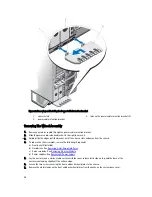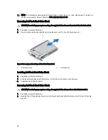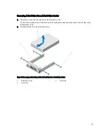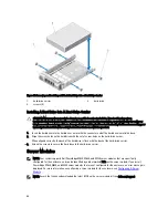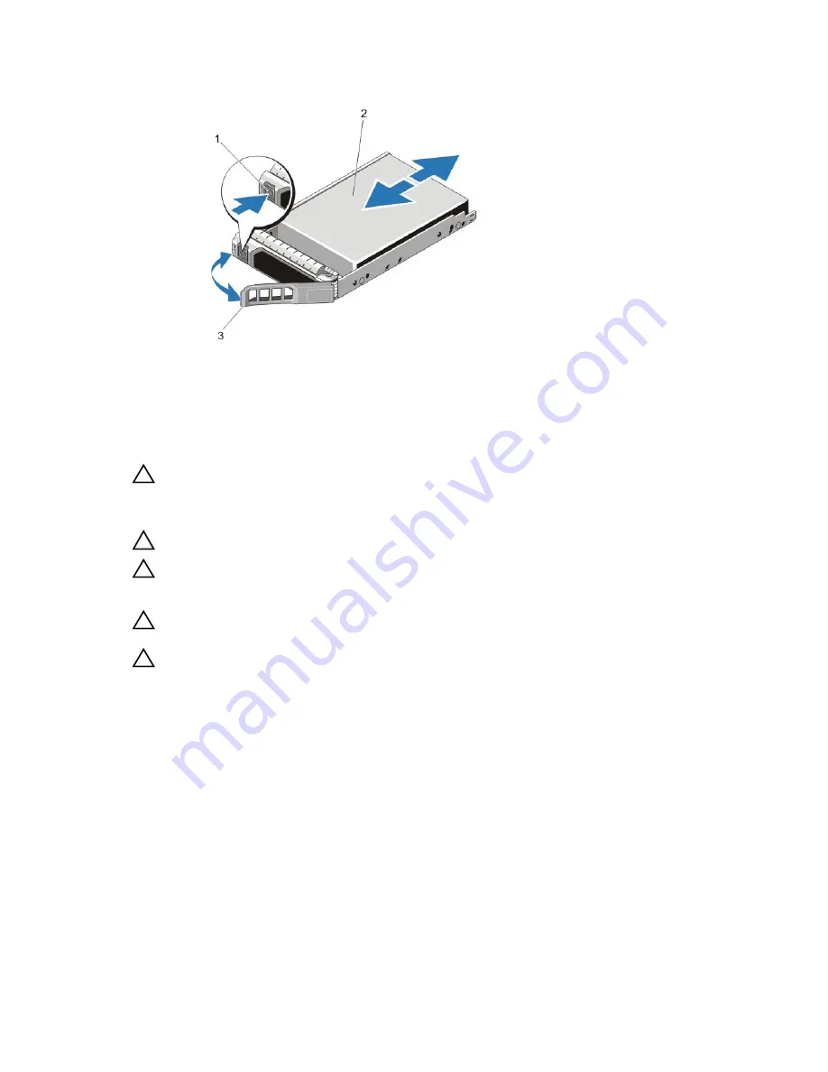
Figure 33. Removing and Installing a Hot-Swap Hard Drive
1.
release button
2.
hard drive
3.
hard-drive carrier handle
Installing A Hot-Swap Hard Drive
CAUTION: Many repairs may only be done by a certified service technician. You should only perform
troubleshooting and simple repairs as authorized in your product documentation, or as directed by the online or
telephone service and support team. Damage due to servicing that is not authorized by Dell is not covered by your
warranty. Read and follow the safety instructions that came with the product.
CAUTION: Use only hard drives that have been tested and approved for use with the hard-drive backplane.
CAUTION: When installing a hard drive, ensure that the adjacent drives are installed properly. Inserting a hard-
drive carrier and attempting to lock its handle next to a partially installed carrier can damage the partially installed
carrier's shield spring and make it unusable.
CAUTION: To prevent data loss, ensure that your operating system supports hot-swap drive installation. See the
documentation supplied with your operating system.
CAUTION: When a replacement hot-swappable hard drive is installed and the system is powered on, the hard
drive automatically begins to rebuild. Make absolutely sure that the replacement hard drive is blank or contains
data that you wish to have over-written. Any data on the replacement hard drive is immediately lost after the hard
drive is installed.
1.
If installed, remove the front bezel.
2.
If a hard-drive blank is installed in the hard-drive slot, remove it.
3.
Install a hard drive in the hard-drive carrier.
4.
Press the release button on the front of the hard-drive carrier and open the hard-drive carrier handle.
5.
Insert the hard-drive carrier into the hard-drive slot until the carrier connects with the backplane.
6.
Close the hard-drive carrier handle to lock the hard drive in place.
7.
If applicable, install the front bezel.
52
Summary of Contents for PowerEdge M520
Page 1: ...Dell PowerEdge VRTX Enclosure Owner s Manual Regulatory Model E22S Regulatory Type E22S001 ...
Page 8: ...8 ...
Page 34: ...34 ...
Page 66: ...Figure 45 Securing the Power Cable Without Wheel Assembly 1 power cable 2 strap 66 ...
Page 148: ...148 ...
Page 151: ...Figure 94 System Board Connectors Back 1 midplane planar connectors 3 151 ...
Page 152: ...152 ...
Page 158: ...158 ...

