DGS-3312SR Stackable Gigabit Layer 3 Switch
14
DGS-3312SR:4#config stacking mode enable
Command: config stacking mode enable
The new stacking mode configuration must be saved and the system restarted
to put the new settings into effect.
If you do not save the changes now, they will be lost.
Saving all configurations to NV-RAM... 15%
Changing the stacking mode in the DGS-3312SR will automatically save the settings and restart the system. It will take a
few minutes to complete the process.
Unit ID Display for Switches in a Switch Stack
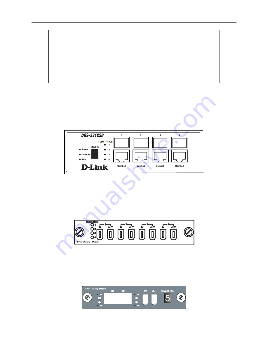
The Stack ID 7-segment LED (as shown below) on the front panel of the DGS-3312SR will always display
F
(15 in hex).
An
F
will also be displayed in the Stack ID LED even if the DGS-3312SR is in standalone mode.
Figure 2-5. DGS-3312SR Front Panel
The Unit ID of individual DES-3226S or DES-3250TG Switches in a Switch stack is determined by the port number of the
port on the DGS-3312SR to which the Switch is connected. The ports on the DGS-3312SR are numbered starting with port
1 from left to right along the front panel of the Switch. For example, the four combination ports next to the Stack NO. LED
are numbered 1 through 4, so if a four port stacking module is installed in the first module slot, the stacking ports will be
numbered 5 through 8. If two stacking modules are installed in the DGS-3312SR, then the stacking ports on the second
module will be numbered 9 through 12.
Figure 2-6. DEM-540 Stacking Module Front Panel
If the a stacking module is installed in the DGS-3312SR’s first module slot, then the first IN/OUT pair in the figure above
will be port 5. If a DES-3226S in a Switch stack is connected to the first stacking port (port number 5 on the DGS-
3312SR), then the Unit ID of the DES-3226S will be 5.
The Unit ID of the DES-3226S or DES-3250TG will be displayed in the STACK NO. LED on the front panel of the
DES-3226S’s or DES-3250TG’s stacking module, as shown below.
Figure 2-7. DES-3226S Stacking Module Front Panel


