


enCoRe™ V CY7C643xx, enCoRe™ V LV CY7C604xx TRM, Document No. 001-32519 Rev *H
32
3. Supervisory ROM (SROM)
This chapter discusses the Supervisory ROM (SROM) functions. For a quick reference of all enCoRe V registers in address
order, refer to the
Register Reference chapter on page 163
3.1
Architectural Description
The SROM holds code that boots a enCoRe V device, cali-
brates circuitry, and performs flash operations. The func-
tions provided by the SROM are called from code stored in
the flash or by device programmers.
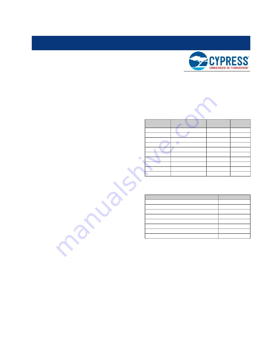
The SROM is used to boot the part and provide interface
functions to the flash blocks.
lists the SROM func-
tions. The SROM functions are accessed by executing the
Supervisory System Call instruction (
SSC
), which has an
opcode of 00h. Before executing the
SSC
, the M8C's accu-
mulator needs to load with the wanted SROM function code
from
.
Attempting to access undefined functions (Reserved func-
tions) causes a
HALT
. The SROM functions execute code
with calls; therefore, the functions require stack space. With
the exception of Reset, all of the SROM functions have a
parameter block in SRAM that you must configure before
executing the
SSC
.
lists all possible parameter block variables. The
meaning of each parameter, with regards to a specific
SROM function, is described later in this chapter. Because
the
SSC
instruction clears the CPU_F PgMode bits, all
parameter block variable addresses are in SRAM Page 0.
The CPU_F value is automatically restored at the end of the
SROM function.
The MVR_PP and MVW_PP pointers are not disabled by
clearing the CPU_F PgMode bits. Therefore, the POINTER
parameter is interpreted as an address in the page indicated
by the
MVI
page pointers, when the supervisory operation is
called. This allows the data buffer used in the supervisory
operation to be located in any SRAM page. (See the
for more details regarding the
MVR_PP and MVW_PP pointers.)
Note
ProtectBlock and EraseAll (described on page
) SROM functions are
not listed in this table because they are dependent on external programming.
Note
CLOCK and DELAY are ignored and are reserved for future use.
Two important variables that are used for all functions are
KEY1 and KEY2. These variables are used to help discrimi-
nate between valid
SSCs
and inadvertent
SSCs
. KEY1 must
always have a value of 3Ah, while KEY2 must have the
same value as the stack pointer when the SROM function
begins execution. This is the SP (Stack Pointer) value when
the
SSC
opcode is executed, plus three. For all SROM func-
tions except SWBootReset, if either of the keys do not
match the expected values, the M8C halts. The SWBootRe-
set function does not check the key values. It only checks to
see if the accumulator's value is 00h.
The following code example puts the correct value in KEY1
and KEY2. The code is preceded by a
HALT
, to force the
Table 3-1. List of SROM Functions
Function Code
Function Name
Required
Stack Space
Page
00h
SWBootReset
0
01h
ReadBlock
7
02h
WriteBlock
7
03h
EraseBlock
5
06h
TableRead
3
07h
CheckSum
4
08h
Calibrate0
4
09h
Calibrate1
3
0Ah
WriteAndVerify
7
0Fh
HWBootReset
3
Table 3-2. SROM Function Variables
Variable Name
SRAM Address
KEY1/RETURN CODE
0,F8h
KEY2
0,F9h
BLOCKID
0,FAh
POINTER
0,FBh
CLOCK
0,FCh
Reserved
0,FDh
DELAY
0,FEh
Reserved
0,FFh


