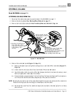

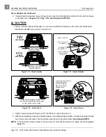


STEERING AND FRONT SUSPENSION
Tie Rod and Drag Link
2001 Pioneer 900 Gasoline Vehicle Maintenance and Service Manual Page 7-13
7
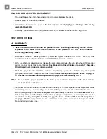
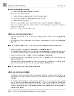
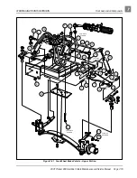
NOTE: When tightening the lock nut (15) make sure the screw (16) does not change adjustment (Figure 7-
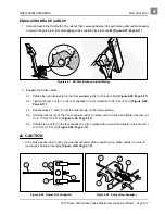
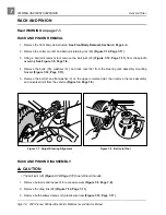
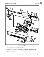
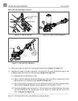
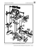
12. Install the dust seal bellows (20) and retaining ring (21) (Figure 7-12, Page 7-11).
13. Install the dust seal bellows (1) and hex nut (29) (Figure 7-12, Page 7-11).
14. Install the universal joint on the pinion. Tighten the bolt to 15 ft-lb (20 N·m).
15. Install new bellows clamps (wire ties) (2) (Figure 7-12, Page 7-11).
16. Install the drag link (28) (Figure 7-12, Page 7-11).
∆ CAUTION
• The ball joint (23) (Figure 7-12, Page 7-11) has left-hand threads.
• The tie rod and drag link have right-hand threads on one end and left-hand threads on the other end.
Right-hand threads are identified by a groove in the tie rod or drag link.
17. Install the ball joint (23) (Figure 7-12, Page 7-11).
18. Adjust the steering. See Steering Adjustment on page 7-7.
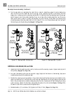
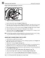
RACK AND PINION INSTALLATION
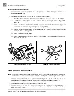
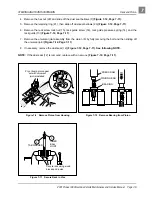
1. Position the steering gear box assembly on the shock and gear support and install the bolts (30), wash-
ers (31), and nuts (32). Do not tighten the mounting bolts (Figure 7-12, Page 7-11).
2. For ease of assembly and to prevent corrosion, apply a light coat of anti-seize and lubricating com-
pound to the splined end of the steering column shaft.
3. Align the flat portion of the steering shaft spline with the bolt hole in the universal joint and then slide
the shaft into the upper universal joint. Install the bolt and lockwasher on the upper universal joint and
tighten it to 15 ft-lb (20 N·m).
4. Tighten the steering rack mounting bolts (30) to 22 ft-lb (29.8 N·m) (Figure 7-12, Page 7-11).
5. Adjust the steering. See Steering Adjustment on page 7-7.
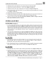
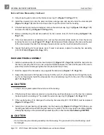
TIE ROD AND DRAG LINK
Read WARNING on page 7-1.
TIE ROD AND DRAG LINK REMOVAL
1. Using locking pliers to hold tie rod and drag link, loosen jam nuts (7 and 12) on tie rod ball joints (Fig-
ure 7-21, Page 7-19) and loosen jam nuts (27 and 29) on the drag link (Figure 7-12, Page 7-11).
2. Remove the cotter pins (22) and ball joint retaining nuts (25 or 20) (Figure 7-12, Page 7-11 or Figure


