FE350 ENGINE
Cylinder Head
Page 13-16 2001 Pioneer 900 Gasoline Vehicle Maintenance and Service Manual
13
∆ CAUTION
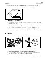
• The 60° seat cutter removes material very quickly. Check the seat outside diameter frequently to
prevent over-cutting.
NOTE: Keep the seat width as close as possible to 0.031 inch (0.8 mm).
2.7. Make a light pass with the 45° cutter to remove any possible burrs at the edge of the seat.
3. After applying a coat of Prussian Blue to the valve face, insert the valve, and snap it closed against the
seat several times. The valve surface should show good contact all the way around. Be sure the valve
seat is centered on the valve face. The position of the valve in the seat is evident after lapping the valve.
4. If the seat does not make proper contact, lap the valve into the seat with a vacuum cup tool.
4.1. Coat the surface of the valve sparingly with a fine lapping compound.
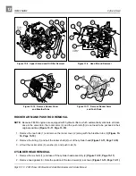
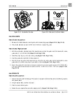
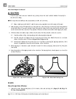
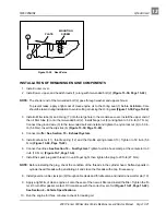
4.2. Use the vacuum cup lapping tool (1) to grip the top of the valve. Rotate the valve in a circular
motion to lap the valve to the seat (Figure 13-27, Page 13-16).
4.3. Lift the valve slightly from the seat every 8 to 10 strokes, continuing the lapping operation until a
uniform ring appears around the entire surface of the valve face.
5. When lapping is completed, wash all parts in solvent to remove lapping compound. Dry the parts
thoroughly.
6. Note the position of the lapping mark on the valve face. The lapping mark should appear on or near the
center of the face.
VALVES
Visual Inspection of Valves
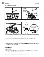
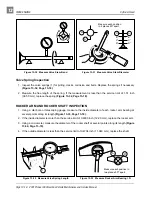
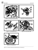
1. Inspect the valve head seating area (1) for erosion, nicks and warping, etc. (Figure 13-28, Page 13-
16). See following NOTE.
Figure 13-27 Lap Valve To Valve Seat
Figure 13-28 Valve Head Seating Area
1
1

