FUEL SYSTEM
Fuel Pump
2001 Pioneer 900 Gasoline Vehicle Maintenance and Service Manual Page 14-21
14
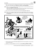
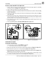
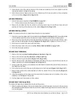
3. Remove the clamp (20) and impulse line (7) from fuel pump (Figure 14-15, Page 14-20).
4. Disconnect the fuel lines (2 and 3) from the pump and plug them to prevent gasoline leakage (Figure
14-15, Page 14-20). See following WARNING.
∆ WARNING
• Carefully drain any fuel remaining in the pump into a container. Add drained fuel back into gas
tank or dispose of properly.
FUEL PUMP DISASSEMBLY
NOTE: A fuel pump rebuild kit is available from Club Car (CCI 1014524). This kit includes all gaskets, dia-
phragms, and valves.
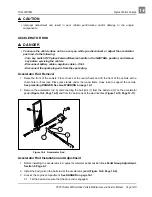
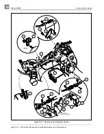
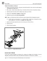
1. Remove four screws (24) and lock washers (25) from front of the fuel pump (Figure 14-16, Page 14-22).
2. Remove the front cover of the fuel pump while holding the rest of the pump intact.
3. Note the orientations of the impulse gasket (27), the diaphragm (28), and the gasket (29), then remove
them from the pump (Figure 14-16, Page 14-22).
∆ CAUTION
• Fuel pump gaskets and diaphragms must be reinstalled in exactly the same positions and
orientations they were in before disassembly, or the pump could leak. If leaking occurs, all new
gaskets and diaphragms must be installed.
4. If the impulse gasket (27) and the diaphragm (28) come off with the front cover, note their orientations
and remove them (Figure 14-16, Page 14-22).
5. Remove the pumping chamber (30) (Figure 14-16, Page 14-22).
6. Remove the back cover (36), the fuel diaphragm (34) and gasket (35) (Figure 14-16, Page 14-22).
FUEL PUMP CLEANING AND INSPECTION
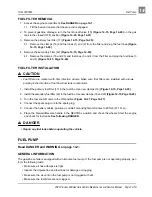
1. Using a nonflammable solvent, clean the front cover, pumping chamber, and back cover. Be sure the
vent on the front cover is clean both inside and out.
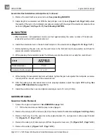
2. Inspect the valve assemblies (31, 32, and 33) and all gaskets and diaphragms for damage (Figure 14-
3. If a valve assembly is damaged, the rubber retaining plug (33) and valve assembly must be replaced
FUEL PUMP ASSEMBLY
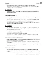
1. Install the fuel gasket (35) and diaphragm (34) on the back cover (36) (Figure 14-16, Page 14-22).
2. Install the valve assembly in the pumping chamber (30) (Figure 14-16, Page 14-22). See following
CAUTION.

