


ELECTRICAL COMPONENTS
Fuel Level Sending Unit
2001 Pioneer 900 Gasoline Vehicle Maintenance and Service Manual Page 12-23
12
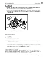
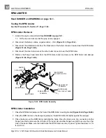
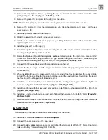
4. Remove the two hex nuts (3) and lock washers (4) from the threaded studs on the back of the gauge.
Remove the mounting bracket (5) from the back side of the gauge and remove the gauge (2) from the dash.
Fuel/Hour Gauge Installation
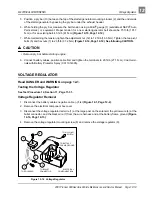
1. Install a new gauge into hole in dash until flange seats against dash (Figure 12-23, Page 12-23).
2. Slide the mounting bracket onto the two threaded studs on the fuel/hour gauge and secure with two
lock washers and two hex nuts. Tighten to 2.5 in-lb (.28 N·m). Place one drop of Loctite™ on each hex
nut. Do not allow Loctite to come into contact with the fuel/hour gauge casing.
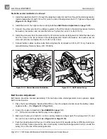
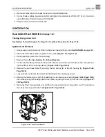
3. Connect the orange wire from the fuel level sending unit to the No. 1 terminal, the blue wire to the No. 2
terminal, the white wire to the No. 4 terminal, and the black wire to the No. 3 terminal on the fuel/hour
gauge. See Wiring Diagram, Section 11, Page 11-6.
4. Coat terminals with Battery Protector Spray (CCI 1014305).
5. Install the center dash in reverse order of removal. Be sure that key switch terminals cannot touch the
frame and that panel is properly seated and snapped in place.
6. Connect battery cables, positive cable first and tighten the terminals to 20 ft-lb (27.1 N·m). Coat termi-
nals with Battery Protector Spray (CCI 1014305).
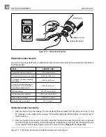
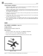
FUEL LEVEL SENDING UNIT
Read DANGER and WARNING on page 12-1.
The fuel level sending unit is an integral part of the fuel tank and should never be removed. Thoroughly test
the fuel level sending unit before replacing the fuel tank.
Testing the Fuel Level Sending Unit
See Test Procedure 25, Section 11, Page 11-39.
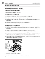
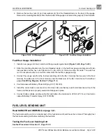
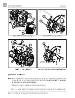
Figure 12-22 Oil Warning Light
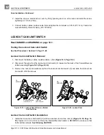
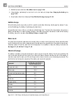
Figure 12-23 Fuel/Hour Gauge Installation
11
CENTER DASH
4
3
5
2