

TROUBLESHOOTING AND ELECTRICAL SYSTEM
Test Procedures
2001 Pioneer 900 Gasoline Vehicle Maintenance and Service Manual Page 11-39
11
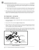
3.3. If the reading is zero, there may be NO continuity across the large posts of the solenoid. See Test
Procedure 6 – Solenoid on page 11-26.
4. If all of the test results are good and the voltage reading is zero, there may be a broken or damaged 6
gauge white wire from the solenoid to the starter/generator. See Test Procedure 8 – Starter/Genera-
tor (Starter Function) on page 11-28.
TEST PROCEDURE 25 – FUEL LEVEL SENDING UNIT
Read DANGER and WARNING on page 11-1.
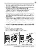
∆ WARNING
• To avoid the possibility of fire or explosion, make sure the fuel tank cap is securely in place
while performing this test procedure.
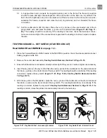
1. Turn the key switch to the OFF position, put the Forward/Reverse handle in the NEUTRAL position, dis-
connect the battery, negative (–) cable first, and chock the wheels.
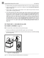
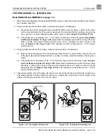
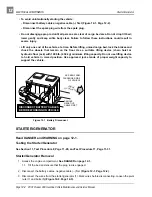
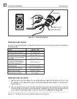
2. Disconnect the orange wire from the center post of the fuel level sending unit.
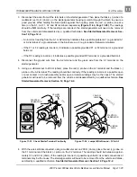
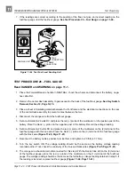
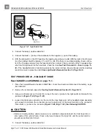
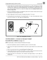
3. With a multimeter set to 2k
Ω
(ohms), place the red (+) probe of the multimeter on the center post of the
sending unit. Place the black (–) probe on the ground connection of the sending unit (Figure 11-44,
Page 11-40).
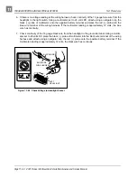
4. The following resistance readings (in ohms) should be obtained depending on the position of the float
inside the fuel tank. The resistance reading will vary according to the exact position of the float. The
chart below may be used as a guideline to determine if the fuel level sending unit is operating correctly.
Make sure the float is at the surface of the fuel in the tank.
5. If the readings are within the specifications listed above, the fuel level sending unit is working properly.
If the readings are incorrect, the fuel level sending unit has failed and the fuel tank must be replaced.
See Fuel Tank Removal, Section 14, Page 14-23.
6. If the readings are correct and the fuel gauge does not function correctly, check the continuity of the
orange wire from the fuel level sending unit to the fuel/hour gauge. Leave the battery disconnected
while checking continuity. Also check the continuity of the yellow wire from the fuel/hour gauge to the
key switch, and the black ground wires at the fuel level sending unit and at the fuel/hour gauge. See
Fuel/Hour Gauge Removal, Section 12, Page 12-22.
FLOAT POSITION
RESISTANCE READING
FUEL GAUGE READINGS
Lower Position (Tank Empty)
240 ± 20
Ω
(ohms)
Empty
Center Position (Tank Half Full)
120 ± 20
Ω
(ohms)
Half Full
Upper Position (Tank Full)
60 ± 20
Ω
(ohms)
Full