ACCELERATOR AND BRAKE PEDAL GROUP
Brake Pedal and Park Brake
Page 5-4 2001 Pioneer 900 Gasoline Vehicle Maintenance and Service Manual
5
Brake Pedal Installation, Continued:
5. Tighten nut (25) on brake stop (24) to 8 ft-lb (9.5 N·m) (Figure 5-2, Page 5-3).
6. Perform pedal group adjustment. See Pedal Group Adjustment on page 5-7.
PARK BRAKE REMOVAL
1. Make sure the key switch is OFF and the Forward/Reverse handle is in NEUTRAL, then disconnect the
battery as instructed in the WARNING on page 5-1.
2. Place chocks under rear wheels.
3. Remove the park brake assembly.
3.1. To remove the park brake rod and pawl assembly (17 through 20), remove the push-on nut (19)
and disconnect the ball joint sleeve (21) from the park brake pedal (29) (Figure 5-2, Page 5-3).
See following NOTE.
NOTE: New push-on nuts (19) and (32) (Figure 5-4, Page 5-4) must be used when reassembling park
brake.
3.2. To remove the park brake pedal (1), remove the push-on retainer nut (32), disconnect the torsion
spring (22) (Figure 5-4, Page 5-4) and slide the pedal off of the shaft. See preceding NOTE.
3.3. Inspect all parts for wear or damage and replace as necessary.
PARK BRAKE INSTALLATION
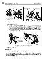
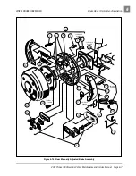
1. From the bottom side of the floorboard, insert park brake rod (17) through brake pedal assembly open-
ing as shown (Figure 5-4, Page 5-4). Then install park brake pawl (35) onto shaft on brake pedal
assembly weldment (10) (Figure 5-4, Page 5-4).
2. Install the spacer (23) and torsion spring (22) on the park brake pedal shaft on the brake pedal weld-
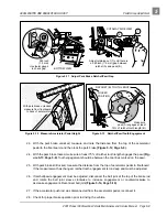
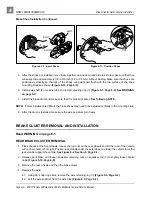
Figure 5-3 Brake Pedal Weldment Through Floor
Figure 5-4 Park Brake Assembly
STOP
1
30
32
30
22
23
10
21
12
17
18
19
35


