UNITIZED TRANSAXLE
Component Disassembly
Page 16-20 2001 Pioneer 900 Gasoline Vehicle Maintenance and Service Manual
16
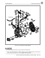
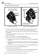
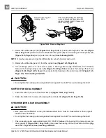
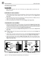
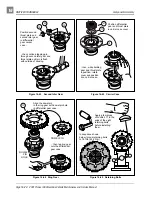
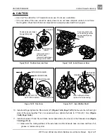
4. Remove the differential pin (88) (Figure 16-5, Page 16-4) by pushing it through from one side (Figure
16-45, Page 16-21). Remove the two differential idler gears (89) and two idler gear thrust plates (85)
(Figure 16-5, Page 16-4) as the pin is driven through. See following NOTE.
NOTE: It may be necessary to drive the differential pin out with hammer and punch.
5. Remove the differential gear (91) from the carrier case (Figure 16-5, Page 16-4).
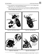
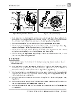
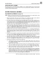
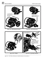
6. If the bearings (79) are to be removed, place a bearing puller wedge attachment (CCI 1012812)
between the bearing and gear case (84) (Figure 16-5, Page 16-4) and press the bearing off as shown
(Figure 16-46, Page 16-21). Repeat the process for the bearing on the carrier cover (87) (Figure 16-5,
Page 16-4). See following CAUTION.
∆ CAUTION
• Do not tighten the bearing puller wedge attachment against the shaft. This could damage the shaft.
SHIFTER FORK DISASSEMBLY
1. Push the shift rod (33) out of the shifter fork (34) (Figure 16-41, Page 16-18).
2. Shake the shifter fork to remove the spring (35) and ball (36) (Figure 16-41, Page 16-18).
SYNCHRONIZER GEAR DISASSEMBLY
∆ CAUTION
• Mark parts for identification as they are disassembled. Parts must be reassembled in their original
locations and orientations.
• Do not tighten the bearing puller wedge attachment against the shaft. This could damage the shaft.
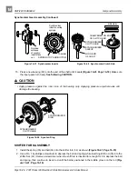
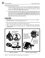
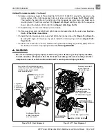
1. Place a bearing puller wedge attachment (CCI 1012812) between the bearing (38) and spur (governor
drive) gear (40) (Figure 16-41, Page 16-18), then press the bearing off the input shaft as shown (Fig-
ure 16-47, Page 16-22). See preceding CAUTION.
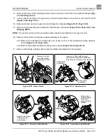
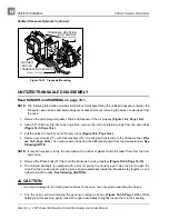
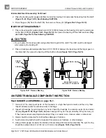
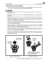
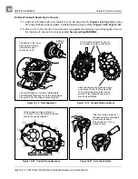
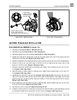
Figure 16-44 Remove Ring Gear
Remove eight ring gear
retaining bolts ...
Then turn differential gear assembly
over and tap around ring gear with a
rubber or plastic mallet to loosen and
remove the ring gear.


