FUEL SYSTEM
How the Carburetor Works
Page 14-2 2001 Pioneer 900 Gasoline Vehicle Maintenance and Service Manual
14
HOW THE CARBURETOR WORKS
MAIN SYSTEM
The main system of the carburetor consists of the main jet, the main nozzle, and the main air passage. The
main system meters fuel to the engine during moderate to heavy load conditions. Fuel flows through the
main jet and into the main nozzle, where it meets air from the main air passage. The resulting mixture flows
out the end of the main nozzle and into the carburetor bore, where it is atomized by high-speed air flow and
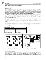
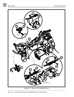
then carried into the engine (Figures 14-1, 14-2 and 14-3, beginning on page 14-2).
During the intake stroke of the engine, a negative pressure (vacuum) is created in the venturi of the carbure-
tor. In this venturi tube, the intake air has high velocity and low static pressure. Subsequently, fuel is drawn
out of the carburetor float chamber, atomized to fine particles, then drawn into the cylinder as a combustible
mixture (Figure 14-2, Page 14-2).
Trouble in the main system is usually indicated by poor performance, or lack of power under heavy load con-
ditions. A dirty or clogged main jet will cause the mixture to become too lean. An overly rich mixture could be
caused by a clogged air passage, clogged air holes in the main nozzle, a loose main jet, or by a loose main
nozzle.
If the engine exhibits symptoms of overly rich or lean fuel mix after all maintenance and adjustments are cor-
rectly performed, the main jet should be replaced. A smaller numbered jet gives a leaner mixture and a larger
numbered jet gives a richer mixture. It is recommended that any change be limited to one jet size difference
from the standard jet.
SLOW SPEED SYSTEM
The slow speed system supplies fuel during low speed running. Low speed running without load requires
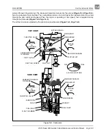
very low intake airflow. The throttle valve (Figure 14-3, Page 14-3) is almost closed when this is the case,
and as high negative pressure is created on the back side of the throttle valve, intake air is drawn in and
STANDARD JETTING
Pilot Air Screw
Middle of Travel
Pilot Jet
45 (x1/100)
Main Jet
82 (x1/100)
Throttle Valve Stop Screw
1200-1250 RPM
Figure 14-1 Fuel Flow Sequence
Figure 14-2 Air/Fuel Mixture
FUEL TANK
FLOAT
CHAMBER
MAIN AIR
PASSAGE
CARBURETOR
BORE
MAIN
NOZZLE
MAIN JET
BLEED PIPE
ENGINE
AIR CLEANER
AIR
FUEL
AIR / FUEL MIXTURE
INTAKE
AIR
CARBURETOR
VENTURI
INTAKE STROKE
OF PISTON

